background image

4  


A


Safety issues 

Observe national safety 

directives and regulations 

for the electrical engineer-

ing trade, in particular: 


IEC 60335-2-69 

EN 60335-2-69 


DIN VDE 105 part 1: 

operation of electrical 

power installations. 


DIN VDE 0701/0702: 

repair, modification and 

testing of electrical installa-

tions. 


Before starting the equip-

ment, be sure to read the 

accompanying user 

manual, and keep it close 

as reference. 


The equipment should 

only be used by persons 

who have been instructed 

in its use and are author-

ized to do so.


Repairs should only be made 

by someone who has re-

ceived proper instructions 

for the job or who is a quali-

fied electrician 
 
WARNING: 
The upper section of the ma-

chine contains live compo-

nents. Contact with live 

components leads to serious 

or even fatal injuries. 
Always disconnect the mains 

plug before disassembly. 

For your own safety


ESD (electrostatic discharge) 
 

Observe the following ESD precautions before any 
repair of or near electronic parts: 
 
• Touch the protective conductor to discharge your own body. 
• Possibly wear an anti-static wrist strap. 
• Use a conducting floor or tabletop. 
• Never touch a circuit board or electronic components - always hold them by the 

plastic or insulation. 
• Transport electronic parts in conductive packaging (e.g. special ESD packages).


 

Summary of Contents for GD 5 BATTERY

Page 1: ...ENGLISH GD 5 Battery Service manual 26 06 2017 GD 5 Battery variants EU UK CH AUS CN US...

Page 2: ...2 2 Index A Preface 3 B Technical data 5 C Troubleshooting 6 D Service repair 7 E Spare parts 16 F Electrical diagram 20...

Page 3: ...r mation sheets These will tell you about any technical modi fications made after publica tion of this repair manual Technical information sheets are a supplement to the spare parts list until a follo...

Page 4: ...e made by someone who has re ceived proper instructions for the job or who is a quali fied electrician WARNING The upper section of the ma chine contains live compo nents Contact with live components...

Page 5: ...5 5 B Technical data GD 5 Battery specifications all variants...

Page 6: ...omplete machine is working correctly No Job done Yes If the machine does start but it is not possible to switch between eco and power boost setting test the re sistance on the switch If switch is ok t...

Page 7: ...7 7 D 1 Change motor unit 9 0 Disassembly 8 3 Change PCB 13 Service repair 2 Change switch cord 12 4 Change battery connector 14 5 Change battery lock 15...

Page 8: ...components Always disconnect the battery before disassembly 2 1 3 Loosen the on off switch to not be connected to the harness use a TX10 bit fig 1 Unscrew the harness fig 2 Unscrew and remove the back...

Page 9: ...following guide in previous section D 0 Unscrew the cable relief fig 1 and disconnect the motor wires from the PCB fig 2 3 1 2 3 WARNING The electric section of the machine contains live components Al...

Page 10: ...the motor unit fig 4 Unscrew and remove the outer co ver fig 5 and the motor cover fig 6 Make notice of how the motor is turned 4 5 6 WARNING The electric section of the machine contains live compone...

Page 11: ...ble the machine backwards Take spe cial notice that the motor housing is placed cor rectly fig 8 7 8 It may be more easy to put the motor co ver back on if the ex haust filter is taken off Remember to...

Page 12: ...on D 0 Unscrew the cable relief fig 1 and disconnect the switch wires from the PCB fig 2 Carefully pull out the cord and replace it Reassemble the machine backwards 2 WARNING The electric section of t...

Page 13: ...ice of how the wires are connected to the PCB disconnect all wires and unscrew the PCB use a TX10 bit fig 1 Change the PCB and repeat the process backwards to assemble the ma chine WARNING The electri...

Page 14: ...rew the brackets holding the battery connector fig 1 Disconnect the wires from the battery connector on the PCB fig 2 3 Replace the battery connector and reassemble the machine 1 2 3 WARNING The elect...

Page 15: ...unit following guide in previous section D 0 Unscrew the battery lock fig 1 Change the battery lock and reas semble the machine WARNING The electric section of the machine contains live components Al...

Page 16: ...16 16 E Spare parts Cassette and electronics...

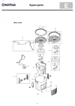
Page 17: ...17 17 E Spare parts Motor parts...

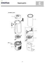
Page 18: ...18 18 E Spare parts Container parts...

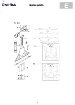
Page 19: ...19 19 E Spare parts Harness...

Page 20: ...20 20 F Electrical diagram GD5 Battery wiring diagram...

Reviews: