15
>20 sec.
110004594
Eng
lis
h (
EN
)
7. Operation procedures
7.1. Start up
7.1.1. New system
Note: The pump should be bled and filled with water
before start.
7.1.2. New System
To prevent problems when starting af new unit, the
system should be rinsed thoroughly through and
vented.
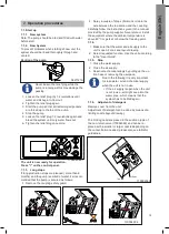
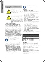
Venting of the pump
Never loosen the relief plug while the
pump is running as this may damage the
packing.
1. Loosen the relief plug (A) 1-2 revolutions until
water and air begin to flow out.
2. Tighten the relief plug again
3. Start the pump so that all remaining air pockets
are forced up to the top of the pump.
4. Stop the pump.
5. Loosen the relief plug 1-2 revolutions again and
bleed the system until only water flows out.
6. Tighten the relief plug once more.
0627121A
DETAIL A
A
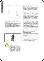
2. Spray a couple of drops of silicone oil onto the
axle between the top section and the coupling.
Carefully follow the instructions given in the manual
provided by the pump supplier. Never store or install
the equipment where the ambient temperature is
above 40°C or gets at or below the freezing point.
7.1.4.
1. Make sure that the water and air supply to the
unit is open. For air see layout drawing.
2. Select requested function. Use the unit according
to the "User Guide".
7.1.5. Stop
1. Close the water supply.
2. Close the air supply.
3. Deactivate chemical supply by pulling up the uc-
tion hose or removing the userpack.
Due to the following it is very important
to close water, air and chemical supply
when the unit is not in use.
•
If the air supply is open when the unit
is not in use - air might seep into the
water pipe - which means that the
system has to be bled again.
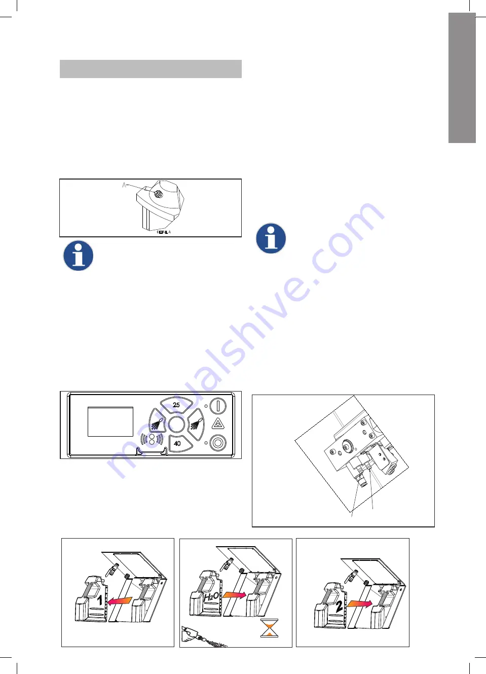
7.1.6. Adjustent of detergent
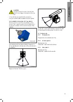
Remove cover from the unit.
Adjustment of detergent can be done by means of a
limiting nozzle (layout drawing).
The limiting nozzle is placed in the suction nipple of
the non-return valve (110004589) and can be re-
placed with a smaller or larger nozzle depending on
the concentration needed, please also see table for
guidelines.
Desinfection
Foam
110004589
110004582-1
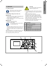
The unit is now ready for operation.
Press "I" on the control panel.
7.1.3. Long stops
If long production stops are planned ( more than 6
months) and the pump is emtied of water, it si recom-
mended that the pump is secured as follows:
1. Remove the coupling safety guard
Summary of Contents for Hybrid Typhoon
Page 1: ...Hybrid Typhoon Directions for use Gebrauchsanweisung Mode d emploi Instrucciones de uso...
Page 80: ......
Page 86: ...8 2 4 5 6 1 3 7 110004550 Hybrid Typhoon...
Page 88: ...Hybrid Typhoon 1 3 2 4 5 110004554...
Page 90: ...17198_30 1 2 3 Hybrid Typhoon...
Page 92: ...Hybrid Typhoon 110004551 1 2...
Page 94: ...Hybrid Typhoon 1 2 3 4 9 8 7 6 5 10 7 8 12 11 13 110004548...
Page 96: ...Hybrid Typhoon 110004552 1 2 3...
Page 98: ...Installation 658 1435 1011 1107 110004599...
Page 100: ...El diagram 110004767E...
Page 101: ...El diagram...
Page 102: ...El diagram...
Page 103: ...110004775D El diagram...
Page 104: ...El diagram...
Page 105: ...El diagram...
Page 107: ...Pump curve 25 bar 50 Hz...
Page 109: ...Layout Hybrid MU...
Page 111: ......

