14
-
FORM NO. 56043055 / HR 2800, HR 2800C / BR 700, BR 700C
WHEEL DRIVE SYSTEM
FRONT
B
A
Solution Control
Lever
Brake Cable
Parking Brake
Slide Lever
WHEEL DRIVE MOTOR ASSEMBLY REMOVAL
1
Turn the key switch (main power) to the OFF position and then disconnect the battery pack connector
(12)
.
2
On the side of the drive motor remove the motor wiring cover and observe the (2) wires (red & black) connected to the motor (terminal
connections for reassembling). Then remove the wires using a 13mm wrench.
3
Remove the brake cable linkage at the brake caliper arm then loosen the brake cable anchor nut and pull the cable away from the
mount bracket.
4
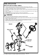
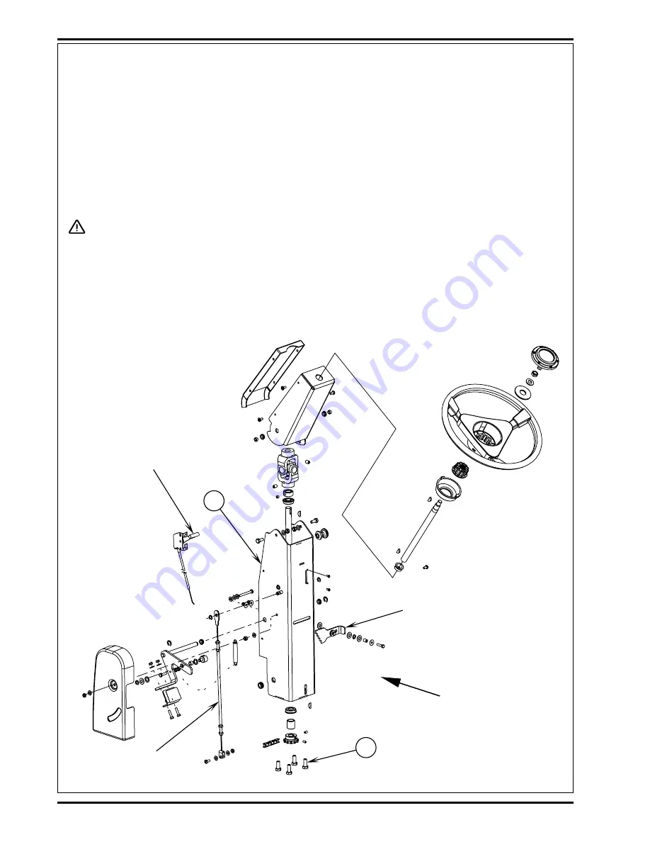
See Fig. 1. Loosen the (4) hex HD Screws
(A)
and push the lower Steering Column
(B)
towards the driver’s seat to release the
steering chain tension.
5
Pry off the spindle nut access cover plate located on top of the drivers compartment floor.
6
Remove the cotter key from the spindle nut and using a 1-5/16 inch socket remove the castle nut from the shaft.
WARNING!
Never work under machine without safety stands or blocking to support the machine.
7
Block rear wheels so machine can’t roll. Then safely jack up or lift the front of the machine about 3-4 inches (76-102 mm) and support
the frame on both sides at the front corners.
8
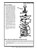
See Figure 2. Pull the motor/wheel assembly out from underneath the machine enough to remove the brake and motor wiring cable
clamps
(C)
&
(D)
from the top of the steer plate. Then finish removing the assembly from the machine.
9
See the
Drive Tire Removal
section for further disassembly steps.
FIGURE 1
revised 2/05
Summary of Contents for Hydro-Retriever 2800 BR700
Page 2: ......


