16
-
FORM NO. 56043055 / HR 2800, HR 2800C / BR 700, BR 700C
WHEEL DRIVE SYSTEM
BRAKE ADJUSTMENT
Before making brake adjustment, inspect brake caliper and rotor for excessive wear and replace brake parts as needed. See
Brake Pad
Replacement
section below, for instructions.
1
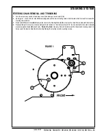
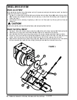
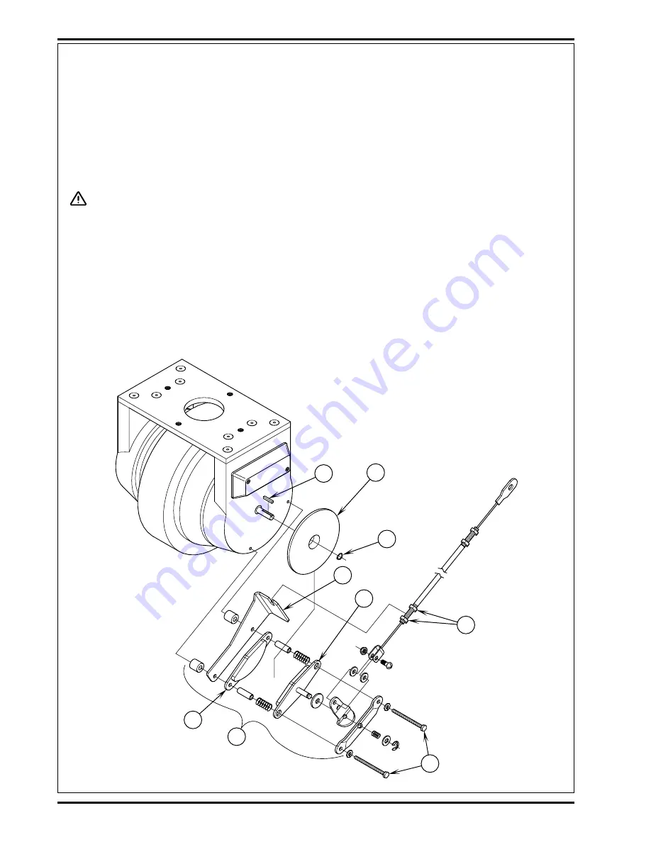
See Figure 3. Loosen both the Locking Nuts
(L)
that secure the brake cable to the Mount Bracket
(M)
(located on the wheel motor).
Note:
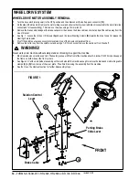
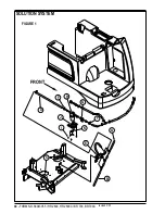
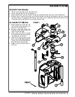
The brake cable is threaded at both ends remove the brake cover on the left side of the steering column if replacement is
needed (See Figure 1).
2
Adjust the brake cable by shortening or lengthening, to obtain one inch of brake pedal travel (free play) before full brake pad
engagement.
CAUTION!
Test-drive the machine and check for positive brake pedal and parking brake functions.
BRAKE PAD REPLACEMENT
1
See Figure 3. Remove the (2) brake caliper mounting Screws
(N)
and then pull the Caliper Assembly
(O)
off the Brake Rotor
(P)
.
2
Separate the (worn) inboard and out board Brake Pads
(Q)
and
(R)
from the caliper assembly and discard.
3
Inspect the Brake Rotor
(P)
for excessive wear (deep grooves) and any signs of warpage (parallelism) replace as needed.
4
Important: To remove the rotor first remove the Retaining Ring
(S)
then carefully pry the rotor off from the motor shaft using (2) large
pry bars. Note: Don’t lose the Key Stock
(T)
which is needed to prevent the rotor from spinning on the motor shaft.
5
Reassemble the caliper assembly as shown using new brake pads.
Note:
Always replace the brake pads as a set. After installing
the brake caliper assembly, readjust the brake setting by following the brake adjustment instructions shown above.
T
P
L
M
R
N
Q
O
S
FIGURE 3
revised 2/05
Summary of Contents for Hydro-Retriever 2800 BR700
Page 2: ......

