FORM NO. 56043055 / HR 2800, HR 2800C / BR 700, BR 700C
- 17
WHEEL DRIVE SYSTEM
U
X
V
Y
Z
CC
W
AA
BB
EE
EE
DD
FF
HH
GG
POTENTIOMETER REMOVAL AND TESTING
WARNING!
Disconnect the machine’s battery pack connector
(12)
before servicing.
Potentiometer Removal
1
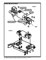
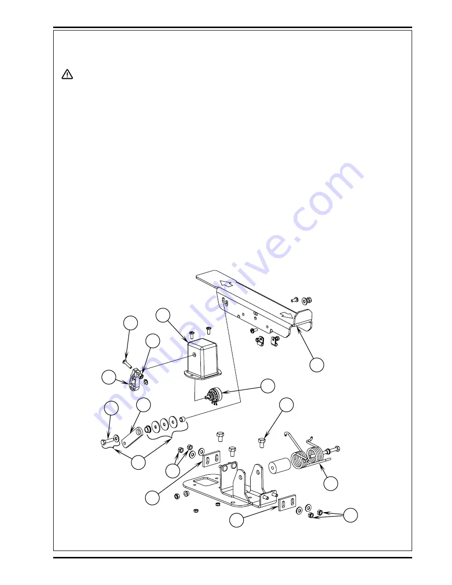
See Figure 4. Remove the (3) Screws
(U)
securing the drive pedal mount assembly to the chassis then carefully lift the pedal
assembly up and lay it on its side.
2
Observe the (3) wires connected to the Drive Pedal Potentiometer (pot)
(BB)
and note the proper wire colors and their terminal
connections for re-assembly. Then disconnect wiring and remove the pedal mount assembly from the machine.
3
Remove the Link Rod
(V)
from the Pedal
(W)
.
Note:
Be careful not to lose the link rod mounting hardware items
(X)
.
4
Loosen the Nut
(Y)
and Screw
(Z)
at the drive pedal Throttle Lever
(AA)
. Then pry the lever off from the end of the item
(BB)
potentiometer shaft. Next remove the pot from the Mount Housing
(CC)
.
Testing the Potentiometer
Note: The pot doesn’t have to be removed from the housing to test.
1
Test the potentiometer using an Ohmmeter (the pot specification is 5K Ohms).
2
Connect the meter leads to each of the outside connections on the potentiometer. The meter should read approximately 5000 Ohms
(plus or minus 500 Ohms).
3
Next, move one of the test leads to the middle connection and turn the stem in both directions. The range of the readings should
be approximately 0-5000 Ohms or 5000-0 Ohms increasing and decreasing through its full range.
4
If you do not get these readings replace the potentiometer.
FIGURE 4
revised 2/05
Summary of Contents for Hydro-Retriever 2800 BR700
Page 2: ......

