FORM NO. 56043055 / HR 2800, HR 2800C / BR 700, BR 700C
- 21
SCRUB BRUSH SYSTEM
SCRUB BRUSH GEARBOX REPLACEMENT
If the need to replace a disc scrub drive gearbox should arise, please follow the re-assembly instructions below.
1
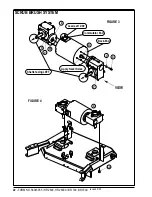
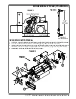
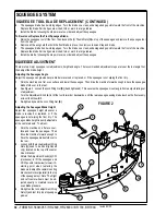
Installing the shaft keys-See Figure 3
Install (1) Shaft Key
(U)
into each end of motor shaft, you may need to use a hammer to complete this operation.
2
Applying Never Seize
Starting with the back-end of the motor. Apply some Never Seize onto the back-end shaft and key. The installation of Never Seize
allows you to remove and replace the gearbox easily if the gearbox fails in the field.
3
Installing the Back-end Gearbox (V)
Visually Line-up the Key
(U)
(installed into the motor shaft) with the keyway
(W)
on the inside of the gearbox. Slide the gearbox
onto the shaft as far as it will go. If the gearbox does not slide on completely (flush with back-end bracket),
DO NOT
use a hammer
to pound the gearbox on the rest of the way. Using a hammer will damage the shaft and bearings inside the gearbox. Carefully
wiggle the gearbox back and forth while pushing the gearbox the rest of the way onto the motor.
4
Installing mounting screws
After the gearbox is completely flush with the back-end bracket of the motor, install 3 Screws
(X)
with lock Washers
(Y)
through the
gearbox mounting flange and into the pre-drilled mounting holes in the back-end bracket.
Important:
Make sure that the gearbox
shaft is pointing in the correct direction before installing the mounting screws. The gearbox shafts should both be pointing left, if
viewing the motor from the back end and the lead terminals are at 12:00. Tighten screws as much as possible with your fingers,
DO NOT
tighten the bolts yet as the gearboxes still need to be lined up.
5
Installing the Comm.-end Gearbox (Z)
Repeat the above process for the comm.-end gearbox.
Remember:
Before installing the mounting screws into the comm.-bracket,
make sure that the gearbox shaft is pointing in the correct direction. Both gearbox shafts should be pointing LEFT, if viewing the
motor from the back-end with the lead terminals at 12:00. Also, remember to not tighten the mounting bolts yet.
6
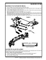
Lining Up the gearboxes-See Figure 4
After you have made sure that the gearbox shafts are pointing in the correct direction and you have installed all 6 mounting screws
(X)
(3 in the back-end gearbox and 3 in the comm.- end gearbox), you must Line-up the gearboxes. Re-install the Gearbox/Motor
Assembly onto the scrub deck as shown. Install and tighten the (6) Screws
(AA)
first and then tighten the (6) Screws
(X)
.
revised 2/05
Summary of Contents for Hydro-Retriever 2800 BR700
Page 2: ......

