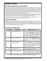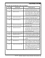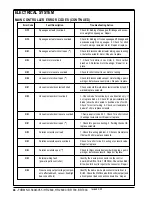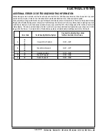
56
-
FORM NO. 56043055 / HR 2800, HR 2800C / BR 700, BR 700C
ELECTRICAL SYSTEM
SERVICE TEST MODE FOR MACHINES AFTER SERIAL NUMBER 1362501
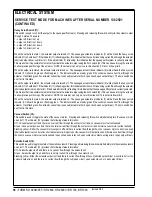
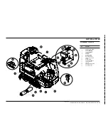
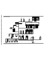
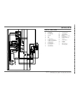
To assist in the troubleshooting and servicing of the electrical system and related components on the 2800/BR700 scrubbers, a special
test mode which allows independent control of the various outputs and monitoring of the various inputs has been incorporated.
To enter the service test mode perform the following steps:
1
Turn the master on/off key switch to the off position.
2
Press and hold the scrub off and normal scrub switches.
3
While holding both switches turn the master on/off key switch to the on position.
4
Continue to hold both switches until the hourmeter/status display shows “test”.
5
Release both switches.
6
The function of each switch and indicator is described below.
7
To exit this mode turn the master on/off key switch to the off position.
Input Indicators:
Battery status red indicator (1):
Speed control status signal. This is an output from the speed control to the main control unit that indicates the status of the speed
control. Normally this indicator will be on whenever the key is on. If there is a speed control fault this indicator will flash the fault code
produced by the speed control. This is an active high signal. (High state = approximately 24 volts, low state = approximately 0 volts).
Battery status yellow indicator (2):
Speed control forward/reverse signal. This is an output from the speed control to the main control unit that indicates when the throttle
has been moved from the neutral position either forward or reverse. The yellow indicator will be lit if this signal is active low. (High
state = approximately 24 volts, low state = approximately 0 volts).
Battery status green indicator (3):
Speed control forward signal. This is an output from the speed control to the main control unit that indicates when the throttle has been
moved in the forward direction. The green indicator will be lit if this signal is active high. (High state = approximately 24 volts, low state
= approximately 0 volts).
Status Display (4):
If no over-current faults are present, the status display will show the battery voltage. This display is accurate to /- 0.15 volts.
Therefore, the voltage displayed may not correlate precisely to a high-accuracy, calibrated voltmeter.
The leftmost digit of the display is used to indicate the current direction for the pad/brush lift actuator and squeegee lift actuators. This
will be described in detail in the sections pertaining to the control of the actuator outputs.
If over-current faults are present, the status display will indicate the fault codes.
Output Controls:
The control panel switches are used to control various output functions of the main control unit. Below is a list of each switch and the
function it controls. Following the list is a detailed description of each function.
Horn switch (20): Used to jog actuators.
Scrub off switch (15): Controls pad/brush motor.
Normal scrub switch (16): Controls pad/brush lift actuator.
Heavy scrub switch (17): Controls squeegee lift actuator.
Vacuum switch (18): Controls vacuum.
Solution switch (19): Controls solution solenoid.
revised 2/05
Summary of Contents for Hydro-Retriever 2800 BR700
Page 2: ......

