FORM NO. 56043055 / Hydro-Retriever
™
2800, 2800C / BR 700, BR 700C
- 61
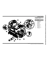
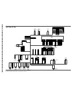
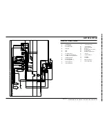
ELECTRICAL SYSTEM
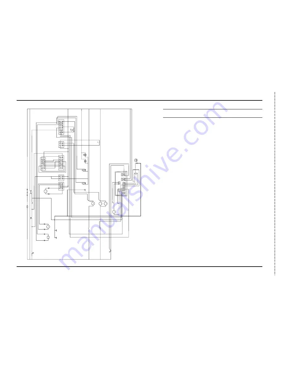
SCHEMATIC / WIRING DIAGRAM
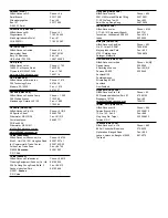
A1
Controller, Speed
A2
Main Control Board
A3
Display PCB Assembly
BT
Battery, 24V
D1
Diode
D2
Diode
F1
Fuse Clamp, 150 Amp
F2
Circuit Breaker, 10 Amp (Control)
F3
Circuit Breaker, 45 Amp (Wheel Drive)
H1
Headlight Kit (Optional)
H2
Beacon kit (Optional)
H3
Horn / Back-Up Alarm 24V
K1
Solenoid (Vac Motor)
K2
Solenoid (Brush Motor)
L1
Valve, Solution Solenoid
M1
Lift Actuator (Brush)
M2
Lift Actuator (Squeegee)
M3
Motor (Vac)
M4
Motor, Brush (Disc) – (Cylindrical)
M5
Motor, Wheel Drive
M6
Motor, Brush (Cylindrical Only)*
R1
Thermistor
R2
Potentiometer 5K Ohm
S1
Switch (Key)
S2
Switch (Seat)
X1
Battery Plug Assembly
X2
Charger Plug Assembly
L1
M1
M
M
BLK
BLK
RED
RED
RED
S1
X1
X1
X2
A2
(+)
(-)
RED/BRN
RED/BRN
ORN/GRN
ORN/GRN
ORN/W
HT
YEL/BRN
GRN
GRN
YEL/W
HT
YEL/BLU
A3
10
1
5
6
GRN/BRN
YEL/GRN
YEL/BLU
YEL/WHT
RED/BRN
RED/BRN
ORN/GRN
GRN
F2
F1
S2
BT
WHT/BLU
BLK/WHT
GRN/BLK
ORN/BLK
ORN/RED
ORN/BLU
VIO/WHT
WHT/ORN
RED/BLK
M2
BLK
BLK
1
4
1
2
3
4
1
7
12
6
BLK
1
2
3
4
1
7
12
6
GRA/RED
ORN
WHT
VIO
J2
J5
J4
J1
H3
BLK BRN
/WHT
RED/WHT
BRN/RED
YEL
(-)
(+)
VIO
/BLK
3
6
M
RT
THERMISTOR
M
CURTIS
PMC
1235
M2
M1
B-
B+
RED
RED
ORN
WHT
GRA
WHT/BRN
BLK
BLK
WHT
/BRN
GRA/RED
D1
D2
VIO/BLK
BLK
RED/GRN
VIO
/BRN
A1
R2
BLK
VIO/BRN
BLK
/YEL
RED/GRN
YEL/RED
BRN
/BLK
BLK/YEL
K1
K2
F3
M3
M4
K1
K2
H1
H2
RED
BLU
BRN
/BLK
YEL/RED
BLK
RED
BLK
WHT
/YEL
WHT
/YEL
VIO
/BRN
VIO/BRN
$
!
'
&
#
#
"
%
"
!
$
M
M5
6
RED
RED/WHT
BRN/WHT
GRA
GRN
VIO
BLK
BLK
BLK
WHT
/BRN
WHT
/BRN
M
M6
GRN
/YEL
GRN/YEL
GRN/YEL
GRN/YEL
GRN/YEL
GRN/YEL
GRN
t
GRN
/YEL
revised 11/02
Summary of Contents for Hydro-Retriever 2800 BR700
Page 2: ......

