background image

Sweden (Prod.)

Nil

fi

 sk-Advance A/S

Phone: +46

Åmål Branch

5321 7500

Strömsbergsgatan Fax: 

+46

Box 127

5321 7595

S-662 23 Åmål

Switzerland (Sales Sub)

Nil

fi

 sk-Advance AG

Phone: +41

Ringsstrasse 19

71 92 38 444

Kirchberg/Industrie Stelzl

Fax: +41

CH-9500 Wil

71 92 35 283

www.nil

fi

 sk-advance.ch

UK (Sales Sub)

Nil

fi

 sk-Advance Limited

Phone: +44

Newmarket Road

1284 763163

Bury St. Edmunds

Fax: +44

UK-Suffolk IP33 3SR

1284 750 562

USA (Prod.)

Nil

fi

 sk-Advance Inc.

Phone: +1 763

14600 21.st Avenue North

745 3500

Plymouth, MN 55447-3408

Fax: +1 763

www.mn.nil

fi

 sk-advance.com

745 3718

USA (Sales Sub)

Nil

fi

 sk-Advance America Inc.

Phone: +1 610

300 Technology Drive

647 6420

Malvern, PA 19355

Fax: +1 610

www.pa.nil

fi

 sk-advance.com

647 6427

Canada (Sales Sub)

Nil

fi

 sk-Advance Canada Comp.

Phone: + 1 905

396 Watline Avenue

712 3260

Mississauga, Ontario L4Z 1X2

Fax: +1 905
712 3255

Australia (Sales Sub)

Nil

fi

 sk-Advance Pty. Ltd.

Phone: +61(0)2

48 Egerton Street

9648 2700

Silverwater, NSW 2128

Fax: +61(0)2

Postal addresse:

9648 2711

PO Box 6046
Silverwater. NSW 1811
info@nil

fi

 sk-advance.com.au

www.nil

fi

 sk-advance.com.au

China (Shenzhen)

Nil

fi

 sk-Advance (Shenzhen) Ltd

Phone: +86 755

Blok 3, Unit 130, 1001 Honghua Road

8359 7937 el.

Int. Commercial & Trade Center

8359 7939-42

Fuitian Free Trade Zone

Fax: +86 755

518038 

Shenzhen

8359 1063

P.R. China

China (Suzhou)

Nil

fi

 sk-Advance Professional 

Phone: +86 512

Cleaning Equipment (Suzhou) Co. Ltd.

8918 5656

306 Su Hong Zhong Road, Build. 2

Fax: +86 512

Suzhou Industrial Park

8918 5666

215021  

Suzhou

P.R. China

Hong Kong (Sales Sub)

Nil

fi

 sk-Advance Ltd.

Phone: +852

2001 HK Worsted Mills Ind’l Bldg.,

2427 5951

31-39 Wo Tong Tsui St.

Fax: +852

Kwai Chung, Hong Kong

2487 5828

Japan (Sales Sub)

Nil

fi

 sk-Advance Inc.

Phone: +8145

3-17-40-101 Chigasaki Higashi

942 7741

Tsuzuki-ku, Yokohama 224-0033

Fax: +8145 

Japan

942 6545

Malaysia (Sales Sub)

Nil

fi

 sk-Advance Sdn Bhd

Phone: +60 3 

No. 21, Jalan SS 25/41

7956 8188

Mayang Industrial Park

Fax: +60 3

47301 Petaling Jaya

7966 6828

Selangor, Malaysia

New Zealand (Sales Sub)

Nil

fi

 sk-Advance Limited

Phone: +64(0)9

Danish House

525 0092

6 Rockridge Avenue

Fax: +64(0)9

Penrose 92-829

525 6440

Auckland1135
Postal addresse:
Private Bag 92 825
Auckland
New Zealand

Singapore (Sales Sub)

Nil

fi

 sk-Advance Pte. Ltd.

Phone: + 65

22,Woodlands Industrial Park E1

6 7599100

Singapore 757740

Fax: +65 

sales@nil

fi

 sk-advance.com.sg

7599133

Taiwan, ROC (Sales Sub)

Nil

fi

 sk-Advance Ltd.

Phone: +886 

Taiwan Branch (H.K.)

2 2239 8812

1F, No. 193,  Sec.2

Fax: +886 

Xing Long Rd., Taipei

2 2239 8832

Taiwan, R.O.C.  

Thailand (Sales Sub)

Nil

fi

 sk-Advance Co. Ltd.

Phone: +66 2

89 Soi Chokechai-Ruammitr

275-5630

Viphavadee-Rangsit Road

Fax: +66 2

Ladyao, Jatuchak, Bangkok 10900

691-4079

Thailand

Summary of Contents for Hydro-Retriever 2800 BR700

Page 1: ...10 99 revised 2 05 Form Number 56043055 Hydro Retriever 2800 BR 700 BR 700C SERVICE MANUAL Advance MODELS 56412002 2800 56412003 2800C Nilfisk MODELS 56412000 BR 700 56412001 BR 700C ...

Page 2: ......

Page 3: ...IRT MAINTENANCE 28 SCRUB BRUSH LIFT ACTUATOR REMOVAL 28 SOLUTION SYSTEM 29 30 SOLUTION SOLENOID VALVE REMOVAL 29 SOLUTION FILTER FLOW CONTROL VALVE ASSEMBLY REMOVAL 29 SOLUTION SYSTEM TROUBLESHOOTING 29 SOLUTION SYSTEM MAINTENANCE 29 RECOVERY SYSTEM 31 32 RECOVERY TANK REMOVAL 31 VACUUM MOTOR REMOVAL 31 VACUUM RECOVERY SYSTEM SERVICE CHECKLIST 32 RECOVERY SYSTEM TROUBLESHOOTING GUIDE 32 SQUEEGEE S...

Page 4: ...ring repair parts for the machine Use the space below to note the Model Number and Serial Number of your machine for future reference MODEL NUMBER SERIAL NUMBER TRANSPORTING THE MACHINE CAUTION Before transporting the machine on an open truck or trailer make sure that The machine is tied down securely see tie down location 22 All access doors and covers are secured The machine parking brake is set...

Page 5: ...ical components Turn the key switch off O and disconnect the batteries before servicing electrical components Never work under a machine without safety blocks or stands to support the machine Do not dispense flammable cleaning agents operate the machine on or near these agents or operate in areas where flammable liquids exist Do not clean this machine with a pressure washer CAUTION This machine is...

Page 6: ...ort 14 grade 8 degrees Cleaning 10 grade 6 degrees Sound Level 75 dB A 20uPa at operator Transport Speed 3 8 mph 6 1 KPH Scrubbing Speed 3 3 mph 5 3 KPH Minimum Aisle Turning Width 65 inches 165 cm Power Source 24VDC Battery Pack Qty 4 6V 395 AH batteries PN 56388582 Battery Weight each 123 lbs 55 8 kg Battery Compartment Size Height 19 1 2 in 49 5 cm Width 16 3 16 in 41 cm Length 23 5 8 in 60 cm ...

Page 7: ...g brake and disconnect the battery before servicing the machine BATTERIES AND CHARGERS Attention See the electrical system manual section for battery installation and charger system requirements WHEEL DRIVE MOTOR GREASE SPECIFICATION If drive motor gear housing grease replacement is needed when repair services are performed Example inspection shows grease contamination Clean gear sets and housing ...

Page 8: ... Min Max A B L 11 Emergency Battery Disconnect Control Knob B D 12 Pre Sweep System Accessory If applicable A B D 13 Tilt Steering Mechanism and Seat Lever A B 14 Optional Accessories headlight safety beacon back up alarm etc D 15 Main Control Board Special Program Options check all applicable program settings reference SVR Manual 56043055 Example Fault Recall Mode Etc Program as needed 16 Battery...

Page 9: ...rive Tire rim fastener torque W 38 Brake Caliper Cable Pad Wear A B W 39 Drive Pedal Linkage neutral return A B 40 Steering Chain lubricate tension A B C 41 Steering Column knob plunger spring A D 42 Rear Wheels W 43 Sweep Debris Tray cylindrical only C NOTE For additional service information see service manual form number 56043055 and operators manual form number 56041449 Defect Codes A needs adj...

Page 10: ...ive Pedal Directional Speed 9 Head Light 10 Drive and Steer Wheel 11 Circuit Breakers KNOW YOUR MACHINE 12 Emergency Stop Switch Battery Disconnect 13 Scrub Brush Deck And Side Skirts 14 Rear Wheel 15 Battery Compartment 16 Recovery Tank Shutoff Float 17 Vacuum Motor Filter Housing 18 Squeegee Assembly 19 Squeegee Casters 20 Solution Filter 21 Recovery Tank Drain Hose 22 Tie Downs 1 Front 2 Rear 1...

Page 11: ...ion System Indicator 29 Vacuum Button 30 Solution Button 31 Battery Condition Indicator 32 Hourmeter Status Display 33 Master On Off Key Switch 34 Scrub Mode Off Indicator 35 Normal Scrub Mode Indicator 36 Heavy Scrub Mode Indicator 37 Vacuum System Indicator 38 Vacuum System Fault Indicator 39 Horn Button CONTROL PANEL 39 38 28 23 33 30 24 26 27 36 32 35 31 34 25 37 29 revised 2 05 ...

Page 12: ...ns for changing both normal and heavy scrub mode pressure adjustments for machines before SN 1362502 NORMAL AND HEAVY SCRUB AFTER SERIAL NUMBER 1362501 Normal Scrub Button 26 Pressing the normal scrub button will enable the scrub system and set the scrub pressure to the last selected value for the normal scrub mode The status display will momentarily display the scrub pressure setting This is indi...

Page 13: ...al the following guidelines apply to the control panel indicators A steady red indicator means that the function is inhibited for some reason For example if the scrub system is off and the operator is not on the seat the scrub system indicator will be red indicating that the system cannot be turned on until the operator is on the seat A flashing red indicator means that a fault has occurred in the...

Page 14: ...GREEN when the key switch is ON This indicator will flash RED if there is a system fault that requires turning the Master ON OFF Key Switch 33 off to reset This indicator will flash fault codes from the Curtis Speed Control if a fault exists This will be accompanied by an Err03 indication on the Hourmeter Status Display 32 DESCRIPTION OF THE BATTERY CONDITION INDICATORS Thebatteryconditionindicato...

Page 15: ...ring chain tension 3 Remove both Master Links B that secure the chain to the Steering Plate C then remove the chain from underneath the machine 4 Reassemble parts in reverse order and adjust chain tension so that there is about 3 16 5 mm total deflection with moderate pressure applied at point D as shown Service Tip Note Use a pry bar or shims between the chassis and steering column to help secure...

Page 16: ...A and push the lower Steering Column B towards the driver s seat to release the steering chain tension 5 Pry off the spindle nut access cover plate located on top of the drivers compartment floor 6 Remove the cotter key from the spindle nut and using a 1 5 16 inch socket remove the castle nut from the shaft WARNING Never work under machine without safety stands or blocking to support the machine 7...

Page 17: ...ints 120 de grees apart to slowly work it from the shaft 6 Using a 5mm hex key wrench remove the 4 Soc HDCapScrews K thatsecurethedrive tiretothecentersectionofthemotorcaseand remove the tire from the motor 7 When reinstalling the drive motor assembly be careful not to damage the spindle threads when lowering the chassis onto the spindle shaft 8 Installthecastlenutandtightennuttoremove any play in...

Page 18: ...for positive brake pedal and parking brake functions BRAKE PAD REPLACEMENT 1 See Figure 3 Remove the 2 brake caliper mounting Screws N and then pull the Caliper Assembly O off the Brake Rotor P 2 Separate the worn inboard and out board Brake Pads Q and R from the caliper assembly and discard 3 Inspect the Brake Rotor P for excessive wear deep grooves and any signs of warpage parallelism replace as...

Page 19: ...dal W Note Be careful not to lose the link rod mounting hardware items X 4 Loosen the Nut Y and Screw Z at the drive pedal Throttle Lever AA Then pry the lever off from the end of the item BB potentiometer shaft Next remove the pot from the Mount Housing CC Testing the Potentiometer Note The pot doesn t have to be removed from the housing to test 1 Test the potentiometer using an Ohmmeter the pot ...

Page 20: ...4 5 Followsteps1 2inreverseorder seePotentiometerRemovalsteps tofinishtheinstallation Thentest drivethemachineforproper speed and FWD REV directional control RED GRN BLK YEL VIO BRN FIGURE 5 DRIVE PEDAL NEUTRAL ADJUSTMENT Ifthedrivepedalhasbeenremovedorreplacedtheneutralpositionforthepedalwillhavetobeset Followthestepsbelowtoaccomplish this WARNING Disconnect the machine s battery pack connector 1...

Page 21: ...nly to be disconnected at the scrub deck mount bracket 4 Cut the wire ties that secure the wiring harness for the solution solenoid valve and scrub brush motor Then remove the two brush motor wires and unplug the wire connector for the solenoid valve Note The scrub brush motor wires are red is positive and black is negative 5 Remove the solution feed hose at the solenoid valve 6 Remove the retaini...

Page 22: ...he proper brush motor installation position is where the two cable mounting bolts wiring connections face the front and right side on the scrub deck platform SCRUB BRUSH GEARBOX REMOVAL Follow steps 1 8 of the Scrub Brush Deck Removal section and steps 1 6 of the Scrub Brush Motor Removal section 1 See Figure 2 Remove the hardware items R S that secure the Hub L to the output shaft on each gearbox...

Page 23: ... completely flush with the back end bracket of the motor install 3 Screws X with lock Washers Y through the gearbox mounting flange and into the pre drilled mounting holes in the back end bracket Important Make sure that the gearbox shaft is pointing in the correct direction before installing the mounting screws The gearbox shafts should both be pointing left if viewing the motor from the back end...

Page 24: ...2 FORM NO 56043055 HR 2800 HR 2800C BR 700 BR 700C SCRUB BRUSH SYSTEM U W X Y Leads at 12 00 V Shafts facing LEFT Z Apply Never Seize VIEW X Y Commutator End Back End FIGURE 3 AA X FIGURE 4 revised 2 05 ...

Page 25: ...rmal usage the blades will wear in time and the operator will notice a small amount of water leaking out underneath the side skirts Replace with new blades as shown in Figure 5 Note Also inspect the front and rear scrub brush skirts as they also help contain the wastewater from splashing onto other machine system components located outside the scrub deck area Skirt replacement 1 Place the scrub de...

Page 26: ...deck mount 6 Disconnect the brush lift motor wire harness at the motor 7 Remove the Retainer Ring EE closest to the motor then slide the upper Mount Pin FF from the chassis mount bracket 8 Remove the complete motor and drive nut assembly from underneath the machine Note Do not turn or reposition the drive nut on the actuator shaft mark if needed IMPORTANT After removing the actuator motor and befo...

Page 27: ... monthly thescrubbrushbristlesforwear thebrushesshouldbereplacedwhenthebristlelengthis1inch 26mm orless SCRUB BRUSH REMOVAL AND INSTALLATION 1 Make sure the key switch is off and disconnect the battery pack connector 12 before servicing 2 To access the brushes swing open both the side skirt assemblies See figure 1 Note The skirt s are held in place by Hairpins A on each side remove the pins and sw...

Page 28: ...both the left and right sides of the machine remove both Retainer Rings O from the arm mount ends P and then separate the support arms from the machine frame 10 Cut the wire ties that secure the wiring harness for the solution solenoid valve and scrub brush motors Next disconnect the two main electrical wires one black one red at the brush motor terminals and then unplug the wire connector for the...

Page 29: ...at the Belt Idler T using a 5 8 inch and 11 16 inch wrenches 3 Disconnect the brush motor wiring at both the Pos Neg terminal connectors and note the correct motor wiring connections for reinstallation Next remove the 3 Screws U and lift the motor out from the frame opening at the end s of the scrub deck 4 Reassemble in reverse order and tension the belt as shown in figure 3 7 36 187 mm Length of ...

Page 30: ... reconnect the battery pack and test the scrub system for proper operation SIDE SKIRT MAINTENANCE General Overview The side skirts function is to channel the wastewater to the rear pick up squeegee helping contain the water within the machine s cleaning path During normal use the blades will wear in time The operator will notice a small amount of water leaking out underneath the side skirts The sk...

Page 31: ... to the Solution Flow Control Valve G and Solution Filter Housing H 3 Remove the 4 Screws I that secure the Solution Bracket J and pull the bracket away from the chassis and then loosen the solution Cable Clamp K 4 Separate the solution cable end from the solution valve handle and complete the removal of the Filter H and Solution Flow Control Valve G from the machine SOLUTION SYSTEM TROUBLESHOOTIN...

Page 32: ...30 FORM NO 56043055 HR 2800 HR 2800C BR 700 BR 700C SOLUTION SYSTEM FRONT F K I J F A B C D G H E FIGURE 1 revised 2 05 ...

Page 33: ...f the rear of the machine to the floor Note This method must be followed in order to release the tank mount brackets from the solution tank retainer pockets FIGURE 1 VACUUM MOTOR REMOVAL 1 Swing forward the seat to open and at the rear of the battery compartment disconnect the vacuum motor wiring harness 2 See Fig 1 Remove the Vacuum Duct Cover A that is secured to the recovery tank by a qty 6 Scr...

Page 34: ...oraleakydrainvalve Avacuum leak below the water line will create turbulence in the recovery tank causing water to enter the vacuum filter and motor Restriction s Anything that blocks the flow of air through the system Restrictions may also be caused by built up debris in the squeegee tool vacuum hoses float cage or wherever the airflow is forced to make a sharp turn Both leaks and restrictions dec...

Page 35: ...ore installing a new motor or drive nut the IN and OUT motor limitswitchesmustbeset orchecked totheircorrectspecifications ReferencetheElectricalsectioninthismanualfortheActuator Drive Nut Adjustments and follow the instructions before replacing the actuator motor 5 After setting the correct actuator nut adjustments for the squeegee lift motor follow the steps 1 4 in reverse order to reassemble SQ...

Page 36: ... Park the machine on a flat even surface and lower the squeegee Then drive the machine forward enough to have the squeegee blades fold over to the rear 2 See Figure 2 Loosen the Lock Wing Nut K hand tightened This secures the squeegee mount angle from easily vibrating out of adjustment 3 Turn the Adjustment Knob L to tilt the tool forward or backwards until the rear squeegee wiping blade touches t...

Page 37: ...n batteries can cause severe injury if allowed to contact the skin or eyes Explosive hydrogen gas is vented from inside the batteries through openings in the battery caps This gas can be ignited by any electrical arc spark or flame When Servicing Batteries Remove all jewelry Do not smoke Wear chemical goggles rubber gloves and a protective apron Work in a well ventilated area Do not allow tools to...

Page 38: ...d Indicator 90 discharge down to 95 discharge Red Indicator 95 discharge down to 99 discharge Flashing Red Indicator 100 discharge scrub system will automatically shut down Important Note See the Main Control Board Special Program Options manual section located in the electrical system and follow the instructions for setting the low voltage cutout threshold CHARGING THE BATTERIES Chargethebatterie...

Page 39: ...ed so there s no need to loosen or remove them for charging Keep the Batteries Clean Use a damp cloth to wipe dirt from the top of the batteries Battery terminals must be clean and tight If the tops of the batteries are wet after charging the batteries have probably been over filled or over charged Note If there is acid on the batteries wash the tops of the batteries with a solution of baking soda...

Page 40: ...is used to change the motor rotation in setting the correct drive nut di mension Instructions for Squeegee Lift Actuator Drive Nut Adjustment 4 See Figure 3 Hold onto the Actuator Drive Nut A and press the rocker switch to run the drive motor and retract the nut towards the motor housing it s IN limit 5 Measure the position of the drive nut on the actuator shaft Manually turn the steel tube to the...

Page 41: ...t as shown with the nut pin pocket away from the motor 2 Follow steps 4 10 in the section labeled Instructions for Squeegee Lift Actuator Drive Nut Adjustment reference previous page 3 Afteradjustingtheactuatordrivenut dimensions followsteps10and11 intheScrubBrushLiftActuatorRemovalmanualsection to reassemble Service Tip See Figure 4 Note the correct orientation of the Spring Housing D when instal...

Page 42: ...PEED CONTROLLER STATUS LIGHT AND DISPLAY The Curtis 1235 speed control will output a fault code if there is a problem associated with the speed control and wheel drive system SeeFigure1 Ifaspeedcontrolfaultoccurs theHourmeter Statusdisplay E willindicate Err03 WhentheErr03isbeingdisplayed and detects a fault the Red Indicator F located by the key switch will flash a special error code sequence unt...

Page 43: ...resent for 5 sec 1 Misadjusted throttle 2 Broken throttle pot 3 Broken throttle mechanism 2 4 OO OOOO Speed limit pot fault 1 Speed limit pot wiper wire broken 2 Broken speed limit pot 3 3 OOO OOO Throttle fault 1 Throttle input wire open 2 Throttle input wire shorted to B or B 3 Throttle pot defective 4 Wrong throttle type selected 4 1 OOOO O Low battery voltage 1 Battery voltage 16 volts 24V mod...

Page 44: ...n the hour meter LED display as they occur If more than one error exists the display will sequence through the error codes at one second intervals The error display will show on the hour meter as the letters Err followed by a two digit code EX Err01 would be a non fatal control fault When troubleshooting any fault description noted with a double asterisk follow the instructions for temporarily dis...

Page 45: ...oid coil overload 1 Check diode for continuity in one direction only if bad replace diode 2 Check for proper installation of diode silver band is wired to positive side of coil 3 Check for wiring problems 4 Check coil resistance if below 41 ohms replace solenoid Err13 Brush solenoid coil severe overload 1 Same as error code 12 2 Shorted coil Replace Err14 Brush solenoid coil open 1 Checkforanopeni...

Page 46: ...oper installation of diode silver band is wired to positive side of coil 3 Check for correct wiring 4 Check coil resistance if below 41 ohms replace solenoid Err30 Vacuum solenoid coil severe overload 1 Same as error code 29 2 Check for a short circuit in wiring or solenoid coil Repair or replace Err31 Vacuum solenoid coil open 1 Check for open in coil wiring 2 If wiring checks OK replace solenoid...

Page 47: ...an internal controller circuit failure before replacing a new main control board Example A shorted solution solenoid valve causes a control fault 01 or 02 which appears on the machine s hour meter status display The service person brings up the fault recall memory and sees additional two digit number s as shown in error code range in the chart below A complete check of that fault area would be com...

Page 48: ...ill be saved and will remain in effect until it is changed again ADJUSTMENT OF NORMAL SCRUB MODE PAD PRESSURE The default pad pressure setting when the normal scrub option is selected is adequate for most scrubbing operations If it is desired to increase or decrease the amount of pad pressure for the normal scrub mode perform the following steps NOTE At the maximum pad pressure setting for the nor...

Page 49: ...off feature such as the vacuum shutting off even if the recovery tank is not full this feature can be disabled To enable or disable this feature perform the following steps 1 Turn the master on off key switch to the off position 2 Press and hold the vacuum switch 3 While holding the vacuum switch turn the master on off key switch to the on position 4 Continue to hold the vacuum switch until the ho...

Page 50: ...ing down hill will cause the squeegee to raise and the solution flow to shut off or allowing the throttle to go to neutral such as coasting down hill will cause the scrub brushes to stop To prevent this the control unit can be placed into a ramp mode If the ramp mode is enabled and selected the scrub brushes will continue to operate as will the vacuum and solution system even if the throttle is in...

Page 51: ...nd hold the scrub off and heavy scrub switches 3 While holding both switches turn the master on off key switch to the on position 4 Continue to hold both switches until the heavy scrub indicator turns green and the hourmeter status display shows dISC or CYL 5 Release both switches 6 Pressing and releasing the heavy scrub switch will now select between the two options For the cylindrical brush unit...

Page 52: ...le the scrub system and set the scrub pressure to the last selected value for the normal scrub mode The status display will momentarily display the scrub pressure setting This is indicated by PA Pressure Adjustment followed by a number Subsequentpressesofthenormalscrubbuttonwillstepthepadpressuresettingthroughtheallowablerangeuptothemaximumvalue programmed for the normal scrub mode Once the maximu...

Page 53: ...play shows adjustable 5 Press and release the scrub off button to save the setting 6 The display will now change to PA followed by a number in the range of normal scrub limit 1 to 7 cylindrical or 9 disc This is the maximum pressure that will be allowed for the heavy scrub mode 7 Press and release the heavy scrub button to select the desired limit 8 Press and release the scrub off button to save t...

Page 54: ...ding both switches turn the master on off key switch to the on position 4 Continue to hold both switches until the hourmeter status display shows donE 5 Release both switches 6 The scrub modes and pressures have now been restored 7 Turn the master on off key switch to the off position SELECTION OF LOW VOLTAGE CUTOUT THRESHOLD FACTORY DEFAULT STD The2800 BR700isequippedwithalowvoltagecutoutfeaturet...

Page 55: ...ic shutoff feature such as the vacuum shutting off even if the recovery tank is not full this feature can be disabled To enable or disable this feature perform the following steps 1 Turn the master on off key switch to the off position 2 Press and hold the vacuum switch 3 While holding the vacuum switch turn the master on off key switch to the on position 4 Continue to hold the vacuum switch until...

Page 56: ...This can make toubleshooting the system difficult This option will allow service personnel to disable some of the fault detection checks to facilitate troubleshooting This will not disable the over current protection on any of the systems To enable or disable fault checking 1 Turn the master on off key switch to the off position 2 Press and hold the scrub off switch and the solution switch 3 While...

Page 57: ...emain in effect until it is changed again Once the ramp mode is enabled it can be selected by pressing and holding either the normal or heavy scrub switches whichever is currently selected for approximately 1 second while scrubbing The scrub motor must already be on to enter the ramp mode While the ramp mode is active the scrub indicator either normal or heavy will alternately flash between green ...

Page 58: ... control unit that indicates when the throttle has been moved from the neutral position either forward or reverse The yellow indicator will be lit if this signal is active low High state approximately 24 volts low state approximately 0 volts Battery status green indicator 3 Speedcontrolforwardsignal Thisisanoutputfromthespeedcontroltothemaincontrolunitthatindicateswhenthethrottlehasbeen moved in t...

Page 59: ...error Iftheupindicator 5 isflashing thisindicatesthatthepad brushliftsystemiscurrentlyselected Thismeans thatitispossibletomomentarilyactivatetheactuatoroutputusingthehornswitch 20 Thiscanbeusedtojogtheactuatortoallowprecise positioning of the actuator NOTE the actuator can only move in this situation if it is not at its up limit Whentheoutputisinstate2 theactuatoroutputisturnedon Thepadactuatordo...

Page 60: ...used to jog the actuator to allow precise positioning of the actuator NOTE the actuator can only move in this situation if it is not at its down limit When the output is in state 4 the actuator output is turned on The squeegee actuator up indicator 7 will be lit and the heavy scrub indicator 11 should be green or flashing green The indicator will be a steady green if the control senses current flo...

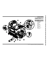
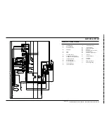
Page 61: ...Contactor Vac Motor 5 150 Amp Fuse 6 Wheel Motor 7 Horn Back Up Alarm 8 Water Solenoid Valve 9 Brush Lift Actuator Motor 10 Squeegee Lift Actuator Motor 11 Vac Motor 12 Brush Motor Disc 13 Brush Motors Cylindrical 14 Throttle Potentiometer 15 Seat Switch 16 Emergency Disconnect Battery 17 Circuit Breaker 10 Amp 18 Circuit Breaker 45 Amp COMPONENT LOCATION revised 11 02 ...

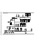
Page 62: ... BLK 0H A BLK 0J A CABLE P N 56412181 BLK THERMISTOR LEAD THERMISTOR LEAD WHT ORN 3A A VIO BLK 70A A YEL BRN 41A A GRA RED 82A A ORN WHT 39A A BRN RED 12A A VIO 7A A RED WHT 29A A GRN 5B A YEL 4A A BRN WHT 19A A HORN BRUSH MOTOR SEAT SWITCH S2 M4 M THERMISTOR VACUUM MOTOR WARNING STROBE LIGHT OPTIONAL ACTUATOR MOTOR SQUEEGEE UP DN ACTUATOR MOTOR BRUSH UP DN SOLUTION SOLENOID VALVE WHEEL DRIVE MOTO...

Page 63: ...lug Assembly X2 Charger Plug Assembly L1 M1 M M BLK BLK RED RED RED S1 X1 X1 X2 A2 RED BRN RED BRN ORN GRN ORN GRN ORN WHT YEL BRN GRN GRN YEL WHT YEL BLU A3 10 1 5 6 GRN BRN YEL GRN YEL BLU YEL WHT RED BRN RED BRN ORN GRN GRN F2 F1 S2 BT WHT BLU BLK WHT GRN BLK ORN BLK ORN RED ORN BLU VIO WHT WHT ORN RED BLK M2 BLK BLK 1 4 1 2 3 4 1 7 12 6 BLK 1 2 3 4 1 7 12 6 GRA RED ORN WHT VIO J2 J5 J4 J1 H3 B...

Page 64: ...Advance A E Tel 30 8 Thoukididou Str 210 963 3443 Argioupoli Fax 30 Gr 164 52 Athens 210 965 0975 Greece Holland Sales Sub Nilfisk Advance B V Phone 31 Camerastraat 9 2e verdieping 36 546 07 00 1322 BB Almere Fax 31 Postbus 60112 36 523 51 48 1320 AC Almere www nilfisk advance nl Ireland Sales Sub Nilfisk Advance Limited Phone 35 28 Sandyford Office Park 3 12 94 38 38 Sandyford Dublin 18 Fax 35 Ir...

Page 65: ...42 Fuitian Free Trade Zone Fax 86 755 518038 Shenzhen 8359 1063 P R China China Suzhou Nilfisk Advance Professional Phone 86 512 Cleaning Equipment Suzhou Co Ltd 8918 5656 306 Su Hong Zhong Road Build 2 Fax 86 512 Suzhou Industrial Park 8918 5666 215021 Suzhou P R China Hong Kong Sales Sub Nilfisk Advance Ltd Phone 852 2001 HK Worsted Mills Ind l Bldg 2427 5951 31 39 Wo Tong Tsui St Fax 852 Kwai C...

Page 66: ...www nilfisk advance com 2005 Printed in USA ...

Reviews: