Scrub System, Disc
79
Service Manual – Scrubtec R 253 - RA40
Scrub System, Disc
Functional Description
The disc brush system can be started by the operator
The disc brush turn counter-clockwise
The rotating brush system cleans the surface of the
floor. The main component of the brush system is the
deck where the brush or the pad-holder with pad suit-
able for the type of surface to be cleaned is installed
The brush deck is installed on a frame to which the
electrical actuator and the four levers for connection
to the frame integrated with the brush motor is cou-
pled
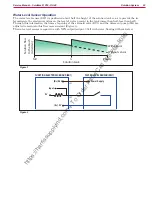
The electrical actuator (M5), with limit microswitches,
lifts and lowers the deck The operating and washing
pressure depends on the weight of the deck The ac-
tuator also permits the extra pressure function Extra
pressure is selected via the button on the dashboard
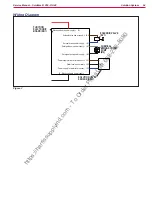
Brush rotation occurs only when the brush motor
(M1) is driven by the function electronic board follow-
ing activation of the accelerator pedal microswitch
The brush system uses the solution to wash the floor.
In case of brush motor overload, a safety system stops
the brushes after about one minute of continuous
overload
If the overload takes place when the extra pressure
function is on, the system automatically turns the ex-
tra pressure function off If the overload persists, the
brush stops
The overload is detected by monitoring the current
flow sum on the brush motor. The current is mea
-
sured by verifying the voltage drop through the brush
system fuse (F1) If the voltage drop reaches the val-
ue stored in the parameter “VS2” (default = 70 mV),
the display shows the alarm message: WARNING
ALARM F2, and if the overload persists, the brush
motor will stop following a delay which varies on the
basis of the extent of the overload
To start scrubbing again after a brush stop due to
overload, turn the machine off Then restart the ma-
chine by turn the ignition key to “I”
To work properly, the brush motor (M1) needs the fol-
lowing:
• Driver’s seat microswitch closed
• Brush function on
• Forward pedal pressed
• Battery level not critical, display icon without
segments and flashing outline.
RPM Brush Reduction Function
This function, controlled by the function board, ad-
justs the brush motor speed and prevents (example:
on very smooth floors) the excessive brush rotation
speed causes water splashing outside of the cleaning
area
If the brush motor current remains below the param-
eterized threshold with the RPM parameter, the mo-
tor is powered by reduced voltage of 20,0V
If the brush motor current exceeds the value of pa-
rameterized threshold, the motor is supplied at 100%
by the battery voltage
https://harrissupplyind.com - To Order Parts Call 608-268-8080


