Control System
16
Service Manual – SC351
Control System
Functional Description
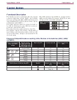
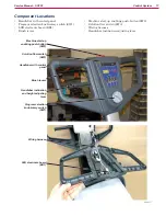
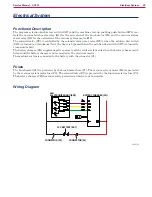
The function control is performed with the program
selection knob/rotary switch (SW1), the machine
start-up enabling push-button (SW2) (which must be
used simultaneously with the brush levers) and the
solution flow switch (SW3).
The switch outputs controls the relevant outputs: re-
lay (K1) for brush motor, relay (K2) for vacuum sys-
tem motor, solenoid valve (EV)
The control circuit are protected by the fuse (F3)
The negative output of the battery charger (B2) al-
lows function activation when battery level is suffi
-
cient and the battery charger is not connected to the
electrical mains
The LED electronic board (EB1) is equipped with 3
LEDs which indicate the battery charge level, both
during operation and while recharging:
Battery charge level
LED display
Diagram of Output Activation according to the Position of the Switches (SW1), (SW2)
and (SW3)
Program selection knob/
rotary switch (SW1)
settings
Machine start-up
enabling push-button
(SW2) settings (with
brush activation levers)
Brush motor (M1)
Solenoid valve (EV)
Vacuum system motor
(M2)
O
Pressed/released
Off
Off
Off
Released
Off
Off
On
Pressed
On
On
On
Released
Off
Off
Off
Pressed
On
On
Off
Released/
Off
Off
On
Pressed
On
Off
On
Solution flow push-button setting (SW3)
Symbols
Solenoid valve ON time
(EV)
Solenoid valve OFF time
(EV)
0
2 sec
2 sec
1
Always ON
-


