Solution System
49
Service Manual – SC351
Solution System
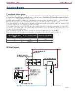
Functional Description
The solution system supplies the detergent to the brush when cleaning the floor. The solution tank is also the
main machine body There is a manual valve on the left side of the tank to close the water supply whenever
maintenance must be performed on the machine
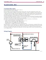
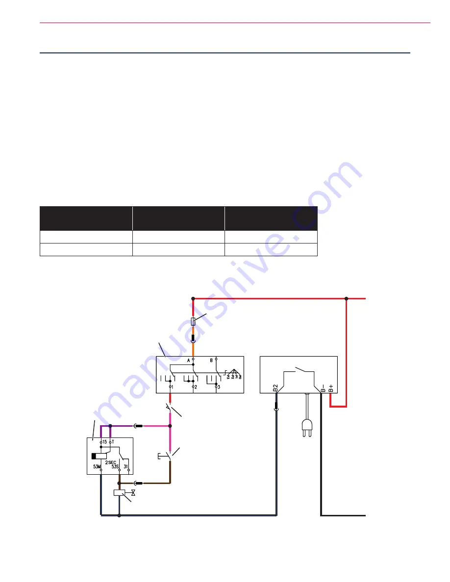
The detergent quantity is adjusted by the operator with the solution flow switch (SW3). The solution flows
from the tank to the tap, through the filter and solenoid valve (EV) and then to the brush deck.
The solenoid valve (EV) is driven by the program selection knob/rotary switch (SW1) when it is turned to 1 or
2, and the machine start-up enabling push-button (SW2)
When the solution flow switch (SW3) is open the solenoid valve (EV) is driven by solenoid valve timer (KT1)
(2 sec. ON - 2 sec. OFF). When the solution flow switch (SW3) is closed the solenoid valve (EV) is always on
(by-pass the solenoid valve timer)
The circuit is protected by the function selector fuse (F3) on the LED electronic board (EB1)
The solenoid valve (EV) opening and closing time, according to the water flow, are shown below:
Solution flow switch (SW3)
setting
Solenoid valve (EV) ON time
Solenoid valve (EV) OFF time
0
2 sec
2 sec
1
Always ON
-
Wiring Diagram
SOLENOID VALVE (EV)
FUNCTION SELECTOR
FUSE (F3)
SOLENOID VALVE
TIMER (KT1)
SOLUTION FLOW
SWITCH (SW3)
BATTERY CHARGER (CH)
MACHINE START-UP
ENABLING
PUSH-BUTTON (SW2)
PROGRAM SELECTION
KNOB/ROTARY SWITCH (SW1)
P100806

