Electrical System - Battery Version
33
Service Manual – SC450
Electrical System - Battery Version
Functional Description
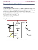
Basically the electrical system consists of a function
electronic board (EB1) which determines the brush
and vacuum system motor activation by means of the
relevant switches (SW1) and (SW2), disabling them
when the battery voltage drops below the battery
safety threshold value
The battery is connected to the system by means of
the ANDERSON POWER connector (C1)
The on-board battery charger (CH) is connected to the
battery with the red (+) and black (-) connector (C2)
and supplies the enabling signal (+24V) to activate
the machine functions only when its yellow connec-
tor (C2) is disconnected from the electrical mains
When the battery charger is connected to the electri-
cal mains, the battery charger inner relay opens the
contact and stops the enabling signal on the yellow
connector (C2) When the battery charger is not in-
stalled, the yellow connector (C2) is not connected and
the dip-switch on the electronic board (EB1) must be
turned to “NO CH”
For further details, see the descriptions of individual
sub-systems
Fuses
The brush motor circuit is protected from short-cir-
cuits by the 40A fuse (F1) The motor is protected
from overloads by means of the electronic protection
system described in the Function Electronic Board
Specifications chapter.
The vacuum system motor circuit is protected by the
30A blade fuse (F2)
The solenoid valve (EV1) and the function electronic
board (EB1) control circuits are protected by 5A blade
fuses (F3) on the function electronic board (EB1)
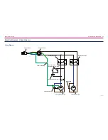
Wiring Diagram
+
-
FUNCTION ELECTRONIC
BOARD (EB1)
F1 - Battery charger power supply
24V BATTERY
(BAT)
CON (C1)
CONNECTOR (C2)
CONNECTOR - (C1)
CONNECTOR (C2)
CONNECTOR (C2)
BATTERY CHARGER (CH)
P200011

