background image

Squeegee System

97

Service Manual – SC450

Specifications

Descriptions / Model

Advance

SC450 20B

Nilfisk

SC450 53B

SC450 53E

Squeegee width

30 in (760 mm)

Summary of Contents for SC450

Page 1: ...SC450 11 12 Revised 4 14 2 Form No 9099600000 Service Manual Advance SC450 9087331020 Nilfisk SC450 9087330020 9087370020 Nilfisk SC450 9087332020 9087372020 English ...

Page 2: ...nt 16 Technical Data Battery Version 17 Technical Data Cable Version 18 Dimensions 19 Maintenance 20 Scheduled Maintenance Table 20 Control System Battery Version 21 Functional Description 21 Wiring Diagram 21 Component Location 22 Removal and Installation 23 Specifications 26 Connectors on the Function Electronic Board 27 Control System Cable Version 28 Functional Description 28 Wiring Diagram 28...

Page 3: ...ption 61 Wiring Diagram 61 Component Location 62 Maintenance and Adjustments 63 Troubleshooting 65 Removal and Installation 66 Specifications 72 Scrub System Disc Cable Version 73 Functional Description 73 Wiring Diagram 73 Component Location 74 Maintenance and Adjustments 75 Troubleshooting 77 Removal and Installation 78 Specifications 80 Solution System Battery Version 81 Functional Description ...

Page 4: ...Squeegee System 89 Functional Description 89 Component Location 90 Maintenance and Adjustments 91 Troubleshooting 93 Removal and Installation 94 Specifications 96 Wheel System Non Traction 97 Component Location 97 Specifications 98 ...

Page 5: ...hen carrying out maintenance and repairs on the SC450 to guarantee the best cleaning performance and a long working life for the machine Please read this manual carefully before performing any maintenance and repair procedure on the machine Other Reference Manuals Model Product Code Intruction for Use Spare Parts List Advance SC450 BATTERY 9087331020 9099602000 9099603000 Nilfisk SC450 BATTERY 908...

Page 6: ...fying the ma chine model and serial number Please apply Retailer label here Serial Number Label The model name and serial number are marked on the plate see the example to the side Product number and year of production are marked on the same plate This information is useful when requiring machine spare parts Use the following table to write down the machine identification data Model Scrubber Dryer...

Page 7: ...d by properly trained operators only Do not wear jewels when working near electrical components Do not work under the lifted machine if it is not securely fixed Do not operate the machine near toxic dangerous flammable and or explosive powders liquids or vapors This machine is not suitable for collecting dangerous powders BATTERY Version Before performing any cleaning maintenance repair or replace...

Page 8: ...e damage to people or objects Do not bump into shelves or scaffoldings especially where there is a risk of falling objects Do not lean liquid containers on the machine use the relevant can holder The machine working temperature must be between 0 C and 40 C The storage temperature must be between 0 C and 40 C The humidity must be between 30 and 95 When using floor cleaning detergents follow the ins...

Page 9: ... the outlet is properly grounded Do not tamper with the power supply cable plug If the power supply cable plug cannot be con nected to the outlet have new grounded outlet installed by a qualified technician according to the law in force Before connecting the power supply plug to the electrical mains check that frequency and volt age shown on the machine serial number plate match the electrical mai...

Page 10: ...der the lifted machine if it is not securely fixed Machine Transportation Warning Before transporting the machine make sure that All covers are closed The solution and recovery tanks are emptied The batteries are disconnected The machine is securely fastened to the means of transport ...

Page 11: ...der Rear parking wheel Squeegee lifting lowering lever Battery connector red Front wheels on fixed axle Squeegee vacuum hose Recovery water drain hose Solution drain and level check hose Brush Solution tank Recovery tank Recovery tank cover Serial number plate technical data conformity certification Can holder Squeegee Squeegee mounting handwheel Squeegee balance adjusting handwheel Squeegee mount...

Page 12: ...ight forward movement adjusting handwheel Machine in parking position Battery connectio diagram Vacuum grid with automatic shut off float Solution filler neck Foam filter Vacuum system motor Solutio filter Solenoid valve ECO position of the solution flow control lever Batterie Battery caps Water removable filler hose speed adjustin handwheel n n Solution flo control lever s Front wheels on fixed a...

Page 13: ...ight the battery charger is on and batteries are charged Yellow warning light the battery charger is on and batteries are semi discharged Battery charge LEDs indicator Green warning light the battery charger is on and batteries are charged Yellow warning light the battery charger is on and batteries are semi discharged Red warning light the battery charger is on and it is charging the batteries Br...

Page 14: ...ebar Rear parking wheel Squeegee lifting lowering lever Front wheels on fixed axle Squeegee vacuum hose Recovery water drain hose Solution drain and level check hose Brush Solution tank Recovery tank Recovery tank cover Serial number plate technical data conformity certification Can holder Squeegee Squeegee mounting handwheel Squeegee balance adjusting handwheel P200002E ...

Page 15: ...alf open Machine forward Machine straight forward movement adjusting handwheel Machine in parking position Vacuum grid with automatic shut off float Solution filler neck Foam filter Vacuum system motor Solutio filter Solenoid valve ECO position of the solution flow control lever Batterie Water removable filler hose speed adjustin handwheel n Solution flo control lever s Front wheels on fixed axle ...

Page 16: ...SC450 Control Panel Cable Version max 2 Pulsante di azionamento spazzola Pulsante di azionamento spazzola Interruttore spazzola Interruttore impianto di aspirazione Pulsante di azionamento spazzola Pulsante di azionamento spazzola P200004E ...

Page 17: ...top computer charged with the current version of EzParts Adobe Reader and if possible Internet connection Digital Volt Meter DVM Amperometric pliers with possibility of making DC measurements Hydrometer Battery charge tester to check 12V batteries Static control wrist strap Dynamometric wrench set A copy of the Instruction for use and Spare Parts List of the machine to be serviced provided with th...

Page 18: ...ure level at workstation ISO 11201 ISO 4871 EN 60335 2 72 LpA 68 dB A 3 dB A Machine sound pressure level ISO 3744 ISO 4871 EN 60335 2 72 LwA 86 dB A Vibration level at the operator s arms ISO 5349 1 EN 60335 2 72 98 4 in s2 2 5 m s2 Maximum gradient when working 2 IP protection class X4 Protection class electric III Vacuum power 0 44 hp 330 W Vacuum water lift blocked 43 3 inH2 O 1 100 mmH2 O Bru...

Page 19: ...ion flow 0 10 0 42 gpm 0 4 1 6 liters min ECO solution flow 0 10 gpm 0 4 liters min Sound pressure level at workstation ISO 11201 ISO 4871 EN 60335 2 72 LpA 70 dB A 3 dB A Machine sound pressure level ISO 3744 ISO 4871 EN 60335 2 72 LwA 89 dB A Vibration level at the operator s arms ISO 5349 1 EN 60335 2 72 98 4 in s2 2 5 m s2 Maximum gradient when working 2 IP protection class X4 Protection class...

Page 20: ...General Information 20 Service Manual SC450 Dimensions 41 7 in 1 060 mm 30 in 760 mm 46 4 in 1 180 mm P200005 ...

Page 21: ...e defined by the person in charge of the maintenance For instructions on maintenance procedures see the following paragraphs Scheduled Maintenance Table Procedure Daily after using the machine Weekly Every six months Yearly Battery charging battery version Squeegee cleaning Brush pad cleaning Tank and vacuum grid with float cleaning and cover gasket check Power supply cable check cable version Squ...

Page 22: ...J1 3 J1 4 J2 6 Power supply J2 7 Power supply J1 6 Green LED J1 5 Yellow LED J1 4 Red LED J1 7 Common LED J3 1 Solenoid valve J3 2 Solenoid valve J2 5 Brush motor current detection J2 4 Brush motor current detection J1 8 Brush system Switch J1 2 Brush switch activation J1 3 Vacuum system switch F1 Battery charger power supply J2 3 Vacuum system relay power supply J2 2 Brush relay power supply J2 1...

Page 23: ...ation push button SW3 Battery voltage LEDs Function electronic board EB1 LED electronic board EB2 Wiring harness Brush switch SW1 Vacuum system switch SW2 Battery voltage LEDs Function electronic board EB1 Wiring harness LED electronic board EB2 Brush activation push buttons SW3 SW4 Brush activation push buttons SW3 SW4 P200007 ...

Page 24: ...le if equipped from the cable holder 5 Remove the screws A 6 Carefully move the panel B by disengaging the wiring harness grommet C from its housing 7 Disconnect the connectors D of the function electronic board E 8 Disengage the four fasteners F and remove the function electronic board E Assembly 9 Assemble the components in the reverse order of disassembly and note the following When installing ...

Page 25: ...h activation push button B 4 Loosen the ring nut C off the bulkhead connection and push the cable D inside the handlebar as much as possible then pull the cables E with the joints F of the push button B 5 Cut the cables E on the joints F and retrieve the push button B Assembly 6 Assemble the components in the reverse order of disassembly and note the following Restore the connections F by using th...

Page 26: ...ve the screws A and move the brush activation push button B 4 Loosen the ring nut C off the bulkhead connection and push the cable D inside the handlebar as much as possible then pull the cables E with the connectors F of the push buttons B 5 Disconnect the connectors F and retrieve the push buttons B Assembly 6 Assemble the components in the reverse order of disassembly and note the following Bef...

Page 27: ...ue of voltage drop detected the brush motor is stopped To reset the protection the electronic board must be turned off and on with the switches SW1 and SW2 b BATTERY PROTECTION Battery charge status is shown by the 3 LEDs on the LED electronic board EB2 depending on the type of battery WET GEL according to the following diagram WET GEL Green LED on fixed V 21 0 V 22 3 Yellow LED on fixed 21 0 V 20...

Page 28: ...C Common LED EB2 PIN 1 5V 8 KY Brush system switch 24V J2 8 WAY CONNECTOR PIN Description Voltage Ref to B 1 CT Relay power supply 24V 2 BT Brush relay power supply 0V 3 VT Vacuum system relay power supply 0V 4 S Brush motor current detection 0V 5 S Brush motor current detection 0V 6 V Power supply 0V 7 V Power supply 24V 8 BL Not used J3 3 WAY CONNECTOR PIN Description Voltage Ref to B 1 W Soleno...

Page 29: ...directly by the brush switch SW1 the vacuum system switch SW2 and the brush activation push buttons SW3 with SW4 The switches SW1 and SW2 power the function electronic board EB1 Wiring Diagram BRUSH MOTOR RELAY ES1 MAINS FILTER FL1 VACUUM MOTOR M2 VACUUM SWITCH SW2 HANDLE BAR SWITCHES SW3 SW4 BRUSH ACTIVATION PUSH BUTTONS SW3 SW4 P200006C ...

Page 30: ... SW1 Vacuum system switch SW2 Brush activation push buttons SW3 SW4 Mains filter FL1 Brush motor relay ES1 Mains filter FL1 Brush motor relay ES1 Brush switch SW1 Vacuum system switch SW2 Wiring harness Brush activation push buttons SW3 SW4 Brush activation push buttons SW3 SW4 P200007 ...

Page 31: ...the brush activation push button B 3 Loosen the ring nut C off the bulkhead connection and push the cable D inside the handlebar as much as possible then pull the cables E with the joints F of the push button B 4 Cut the cables E on the joints F and retrieve the push button B Assembly 5 Assemble the components in the reverse order of disassembly and note the following Restore the connections F by ...

Page 32: ...he screws A and move the brush activation push button B 3 Loosen the ring nut C off the bulkhead connection and push the cable D inside the handlebar as much as possible then pull the cables E with the connectors F of the push buttons B 4 Disconnect the connectors F and retrieve the push buttons B Assembly 5 Assemble the components in the reverse order of disassembly and note the following Before ...

Page 33: ...mains the battery charger inner relay opens the contact and stops the enabling signal on the yellow connector C2 When the battery charger is not in stalled the yellow connector C2 is not connected and the dip switch on the electronic board EB1 must be turned to NO CH For further details see the descriptions of individual sub systems Fuses The brush motor circuit is protected from short cir cuits b...

Page 34: ... connections Battery charger CH Battery connector C1 Electrical component box Brush fuse F1 Vacuum fuse F2 Control solenoid fuse F3 Batteries BAT Battery connections Battery charger CH Battery connector C1 Electrical component box Brush fuse F1 Control solenoid fuse F2 Vacuum fuse F3 12V 12V P200012 ...

Page 35: ...isconnected The machine factory setting is for GEL batteries If this setting corresponds to the type of batteries installed go to step 7 Otherwise perform steps 2 to 6 2 Move aside the recovery water drain hose 3 Remove the battery charger cable if equipped from the cable holder B 4 Remove the screws C and carefully move aside the panel D by disengaging the grommet E from its housing on the panel ...

Page 36: ... selector I to WET for lead batteries or to GEL for GEL AGM batteries 10 Install the window H and tighten the screws N Battery Installation 11 Remove the recovery tank cover J 12 Install the batteries K on the machine according to the diagram L Warning For a proper machine balance install the batteries in the compartment with the shims M placed on the rear wall 13 Install the recovery tank cover J...

Page 37: ...y from naked flames Do not smoke while charging the batteries Do not reinstall the recovery tank until the battery charging cycle is over Caution Pay careful attention when charging WET batteries as there may be battery fluid leakages The battery fluid is corrosive If it comes in contact with skin or eyes rinse thoroughly with water and consult a physician Caution It indicates a caution related to...

Page 38: ...t be 24 V 6 Disconnect the battery connector A and connect it to the external battery charger 7 Connect the battery charger to the electrical mains 8 After charging disconnect the battery charger from the electrical mains and from the battery connector A 9 For WET batteries only Check the level of electrolyte inside the batteries B and close all the caps C 10 Connect the battery connector A to the...

Page 39: ...rger is connected to the electrical mains all machine functions are automatically cut off If the warning light F on the battery charger control panel stays on the battery charger is charging the batteries 13 When the green warning light G turns on the battery charging is completed 14 When the battery charging is completed disconnect the battery charger cable D from the electrical mains and wind it...

Page 40: ...ped from the cable holder 5 Remove the screws A 6 Carefully move the panel B by disengaging the wiring harness grommet C from its housing 7 Check the following fuses for integrity D Brush deck fuse F1 40 A E Vacuum system fuse F2 30 A F Electronic board fuse F3 5 A 8 Replace the open fuse when the component that caused deactivation has fully cooled down 9 Engage the grommet C and install the cover...

Page 41: ...21 6 V Brushes Vacuum system OFF Troubleshooting Trouble Possible Causes Remedy The machine is not working The batteries BAT are discharged or its connections are not efficient Charge the batteries or clean repair the connections The batteries BAT are broken Check the battery no load voltage The battery charger CH is broken Replace The fuses F1 F2 F3 are open Replace The wiring harness is cut or p...

Page 42: ...1 ELECTRONIC BOARD LED EB2 BRUSH MOTOR ELECTROMAGNETIC SWITCH ES1 BRUSH MOTOR ELECTROMAGNETIC SWITCH ES1 VACUUM SYSTEM MOTOR RELAY ES2 VACUUM SYSTEM MOTOR RELAY ES2 SOLUTION SOLENOID VALVE EV1 BRUSH MOTOR FUSE F1 VACUUM SYSTEM MOTOR FUSE F2 SOLENOID VALVE AND ELECTRONIC BOARD FUSE F3 BRUSH MOTOR M1 VACUUM SYSTEM MOTOR M2 BRUSH SWITCH SW1 VACUUM SYSTEM SWITCH SW2 BRUSH ACTIVATION PUSH BUTTONS SW3 S...

Page 43: ...del Advance SC450 20B Nilfisk SC450 53B Total absorbed power 34 A 0 8 kW Battery compartment size width x length x height 350 x 350 x 300 mm 13 7 x 13 7 x 11 8 in Battery voltage 24 V Standard batteries 2 Dry 12 V 70 Ah C5 Battery charger 100 240 VAC Work autonomy standard batteries 2 hour ...

Page 44: ...al System Cable Version Wiring Diagram SUPPRESSION FILTER C1 BRUSH MOTOR RELAY ES1 SOLENOID VALVE EV1 MAINS FILTER FL1 HEART SCREW HS DISC BRUSH MOTOR M1 VACUUM MOTOR M2 MAINS PLUG PL BRUSH SWITCH SW1 VACUUM SWITCH SW2 BRUSH ACTIVATION PUSH BUTTONS SW3 SW4 P200011C ...

Page 45: ...Electrical System Cable Version 45 Service Manual SC450 Specifications Descriptions Model Nilfisk SC450 53E Total absorbed power 7 5 A 1 7 kW Power supply 230 V 50 60 Hz ...

Page 46: ...y the electronic board EB1 when the switch SW2 is closed The circuit is protected by the vacuum fuse F2 The automatic float in the vacuum grid stops vacuum system motor M2 from collecting any liquids When the automatic float closes and shuts down the vacuum system the vacuum system motor noise will increase and the floor will not be dried When the recovery tank is full it can be emptied through th...

Page 47: ...over gasket Recovery water drain hose Recovery water vacuum hose Vacuum system motor M2 Electrical component box Vacuum fuse F2 Relay ES2 Relay ES2 Electrical component box Fuse F2 Recovery tank Vacuum grid with automatic shut off float Recovery tank cover Cover gasket Recovery water drain hose Recovery water vacuum hose Vacuum system motor M2 P200018 ...

Page 48: ...necessary remove the grid C clean it carefully and reinstall it If necessary clean also the solution tank Drain the water from the tanks with the relevant drain hoses 5 Check the recovery tank cover gasket D for integrity The gasket D must be in good shape as it is necessary for the recovery tank stay sealed If necessary replace the gasket D by removing it from its housing When assembling the new ...

Page 49: ...relay ES2 is broken Replace The recovery water vacuuming is insufficient or there is no vacuuming The vacuum grid with automatic shut off float is activated because the recovery tank is full Drain the recovery tank The vacuum grid is dirty Clean The tank cover is not correctly positioned Adjust The tank cover gasket is not efficient Clean replace The vacuum system motor filter is dirty Clean The v...

Page 50: ... motor amperage is 13 17 A at 24 V Turn off the vacuum system Remove the Amp clamp A If the amperage is higher perform the following procedures to detect and correct the abnormal input Check that the vacuum fuse F2 is properly positioned Check the condition of the vacuum system motor carbon brushes Remove the vacuum system motor see the procedure in the Vacuum System Motor Disassembly As sembly pa...

Page 51: ...e the soldering D between both lead in wires E 5 Disconnect the lead in wires E 6 Remove the screws F and remove the carbon brushes G 7 Check the carbon brushes D for wear The carbon brushes are worn when The contact with the motor armature is insufficient The contact surface is not even The stroke is less than 0 12 in 3 mm The thrust spring is broken etc In this cases replace both motor carbon br...

Page 52: ...y water tank 2 Loosen the fastener A and disconnect the hose B from the vacuum system motor below 3 Remove the screws C and remove the cover D 4 Disconnect the connector E and remove the vacuum system motor F by lifting it Assembly 5 Assemble the components in the reverse order of disassembly B A C D E F F C C P200022 ...

Page 53: ... Version 53 Service Manual SC450 Specifications Descriptions Model Advance SC450 20B Nilfisk SC450 53B Recovery tank capacity 11 9 US gal 45 liters Vacuum power 0 44 hp 330 W Vacuum water lift blocked 43 3 inH2 O 1 100 mmH2 O ...

Page 54: ...by the airflow created by vacuum motor M2 The dirty water is piped into the recovery tank while the airflow continues to the vacuum fan The vacuum system motor M2 is supplied by the switch SW2 The automatic float in the vacuum grid stops vacuum system motor M2 from collecting any liquids When the automatic float closes and shuts down the vacuum system the vacuum system motor noise will increase an...

Page 55: ...utomatic shut off float Recovery tank cover Cover gasket Recovery water drain hose Recovery water vacuum hose Vacuum system motor M2 Recovery tank Vacuum grid with automatic shut off float Recovery tank cover Cover gasket Recovery water drain hose Recovery water vacuum hose Vacuum system motor M2 P200018C ...

Page 56: ...ecessary remove the grid C clean it carefully and reinstall it If necessary clean also the solution tank Drain the water from the tanks with the relevant drain hoses 5 Check the recovery tank cover gasket D for integrity The gasket D must be in good shape as it is necessary for the recovery tank stay sealed If necessary replace the gasket D by removing it from its housing When assembling the new g...

Page 57: ...overy water vacuuming is insufficient or there is no vacuuming The vacuum grid with automatic shut off float is activated because the recovery tank is full Drain the recovery tank The vacuum grid is dirty Clean The tank cover is not correctly positioned Adjust The tank cover gasket is not efficient Clean replace The vacuum system motor filter is dirty Clean The vacuum gaskets are damaged or do not...

Page 58: ... check that the vacuum system motor amperage is 2 0 e 3 0 Amp at 230 Vac Turn off the vacuum system Remove the Amp clamp A If the amperage is higher perform the following procedures to detect and correct the abnormal input Check the condition of the vacuum system motor carbon brushes Remove the vacuum system motor see the procedure in the Vacuum System Motor Disassembly As sembly paragraph and che...

Page 59: ... the soldering D between both lead in wires E 5 Disconnect the lead in wires E 6 Remove the screws F and remove the carbon brushes G 7 Check the carbon brushes D for wear The carbon brushes are worn when The contact with the motor armature is insufficient The contact surface is not even The stroke is less than 0 12 in 3 mm The thrust spring is broken etc In this cases replace both motor carbon bru...

Page 60: ... water tank 2 Loosen the fastener A and disconnect the hose B from the vacuum system motor below 3 Remove the screws C and remove the cover D 4 Disconnect the connector E and remove the vacuum system motor F by lifting it Assembly 5 Assemble the components in the reverse order of disassembly B A C D E F F C C P200022 ...

Page 61: ...able Version 61 Service Manual SC450 Specifications Descriptions Model Nilfisk SC450 53E Recovery tank capacity 11 9 US gal 45 liters Vacuum power 0 44 hp 550 W 50 60 Hz Vacuum water lift blocked 0 44 hp 550 W 50 60 Hz ...

Page 62: ...the floor In case of brush motor overload a safety system stops the brushes after about one minute of continuous overload The overload is shown by the three battery warning LEDs flashing simultaneously The overload is detected by monitoring the current flow on the motor The current is measured by check ing the voltage drop through the brush fuse F1 If the voltage drop is higher than 40 mV the 3 ba...

Page 63: ... electromagnetic switch ES1 Brush fuse F1 Machine forward speed adjusting handwheel Machine straight forward movement adjusting handwheel Disc brush deck Brush motor M1 Drive hub Brush electromagnetic switch ES1 Fuse F1 Machine straight forward movement adjusting handwheel Machine forward speed adjusting handwheel P2000024 ...

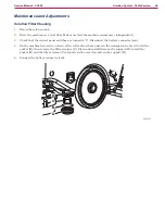
Page 64: ...sure that the machine cannot move independently 2 Check that the control panel switches are turned to 0 3 Remove the brush pad holder A according to the following procedure When the deck is lifted grab the brush pad holder with the hands and turn it first in one direction B and then in the other direction C to release it 4 Clean the brush with water and detergent 5 Check the brush bristles for int...

Page 65: ...t the machine speed with the handwheel A according to the following procedure Turn it counter clockwise to increase the machine speed Turn it clockwise to decrease the machine speed 2 If it is difficult to keep the machine moving straight forwardly because it deviates to the left or to the right adjust the knob B by turning it clockwise or counter clockwise 3 With the machine ready to operate perf...

Page 66: ...perly The brush is excessively worn Replace One brush does not turn Activation of motor overload Restart the machine The motor carbon brushes are worn Replace The motor is faulty Check the motor amperage replace There are ropes or debris restraining the brush rotation Remove and clean The brush fuse F1 is open Replace The motor electromagnetic switch ES1 is damaged Replace The brush motor electrom...

Page 67: ...the amperage is higher perform the following procedures to detect and correct the abnormal input Check that the brush hub is free from foreign materials ropes dirt preventing it from turning Check that the brush fuse F1 is properly positioned Check the condition of the brush motor carbon brushes Remove the brush motor see the procedure in the Brush Motor Disassembly Assembly paragraph and check th...

Page 68: ...cal connection F from the carbon brush assembly 6 Check the carbon brush G for wear The carbon brush is worn when The contact with the motor armature is insufficient The contact surface is not even The stroke is less than 0 12 in 3 mm The thrust spring is broken etc 7 Remove and check the other carbon brush assemblies B by performing steps 3 to 6 8 If necessary disconnect the electrical connection...

Page 69: ...urned to 0 Disconnect the battery connector red 2 Remove the recovery water tank 3 Loosen the fastener A and disconnect the hose B from the vacuum system motor below 4 Remove the screws C and remove the cover D 5 On the brush motor E disengage the rubber caps F then disconnect the electrical connections G of the motor B A E G C F D G C C P2000029 ...

Page 70: ...remove the screws below 7 Lift the machine front side I and keep it lifted 8 Loosen the screws J fastening the solution solenoid valve K 9 Move the solenoid valve K and disconnect the hose L from the solenoid valve by pulling it 10 Recover the brush deck M Assembly 11 Assemble the components in the reverse order of disassembly I L G M K H H J P2000030 ...

Page 71: ...battery connector red 4 Remove the recovery water tank 5 Loosen the fastener A and disconnect the hose B from the vacuum system motor below 6 Remove the screws C and remove the cover D 7 On the brush motor E cut the fastening clamp F of the wiring harness G 8 Move the rubber caps H protecting the electrical connections I 9 Remove the nuts and disconnect the electrical connections I from the motor ...

Page 72: ... brush hub J to protrude slightly from the edge of the hoisting system 11 Remove the screw K 12 Remove the brush hub J if necessary use a sliding hammer puller L 13 Remove the brush motor fastening screws M 14 Lower the hoisting system then remove the brush motor E Assembly 15 Assemble the components in the reverse order of disassembly I J M K M J L P2000032 ...

Page 73: ...rvice Manual SC450 Specifications Descriptions Model Advance SC450 20B Nilfisk SC450 53B Brush diameter 20 in 530 mm Brush pressure with full tank and lowered squeegee 66 lb 30 kg Brush motor power 0 64 hp 480 W Brush rotation speed 154 rpm ...

Page 74: ...ine with a support plate On the support plate there are two handwheels to adjust the machine straight forward movement and speed The brush working pressure is functional to the ma chine designed balance The brush motor M1 is supplied by the electromag netic switch ES1 which is driven by the fu switches SW1 and SW3 with SW4 The system once activated uses the solution coming form the solution system...

Page 75: ... Drive hub Brush electromagnetic switch ES1 Machine forward speed adjusting handwheel Machine straight forward movement adjusting handwheel brush motor relay ES1 Disc brush deck Brush motor M1 Drive hub Machine straight forward movement adjusting handwheel Machine forward speed adjusting handwheel P2000024 ...

Page 76: ...ure that the machine cannot move independently 2 Check that the control panel switches are turned to 0 3 Remove the brush pad holder A according to the following procedure When the deck is lifted grab the brush pad holder with the hands and turn it first in one direction B and then in the other direction C to release it 4 Clean the brush with water and detergent 5 Check the brush bristles for inte...

Page 77: ... the machine speed with the handwheel A according to the following procedure Turn it counter clockwise to increase the machine speed Turn it clockwise to decrease the machine speed 2 If it is difficult to keep the machine moving straight forwardly because it deviates to the left or to the right adjust the knob B by turning it clockwise or counter clockwise 3 With the machine ready to operate perfo...

Page 78: ...h does not turn The motor carbon brushes are worn Replace The motor is faulty Check the motor amperage replace There are ropes or debris restraining the brush rotation Remove and clean The motor electromagnetic switch ES1 is damaged Replace The brush motor electromagnetic switch wiring harness is damaged Repair The brush motor electromagnetic switch wiring harness is damaged Repair ...

Page 79: ...en 2 and 4 Amp at 230 Vac Stop the brush rotation Remove the Amp clamp A If the amperage is higher pes to detect and correct the abnormal input Check that the brush hub is free from foreign materials ropes dirt preventing it from turning Remove the brush motor see the procedure in the Brush Motor Disassembly Assembly paragraph and check the condition of all its components If the above mentioned pr...

Page 80: ...Brush Deck Motor Capacitor Wiring Diagram 230V Internal wiring connections V2 W1 U2 V1 W2 U1 A Starting Capacitor 65 70µF B Working Capacitor 30µF Internal Internal Internal Internal Internal Power cable A Starting Capacitor 65 70µF B Working Capacitor 30µF ...

Page 81: ... Service Manual SC450 Specifications Descriptions Model Nilfisk SC450 53E Brush diameter 20 in 530 mm Brush pressure with full tank and lowered squeegee 88 lb 40 kg Brush motor power 0 64 hp 1 100 W 50 60 Hz Brush rotation speed 150 rpm ...

Page 82: ...and then to the brush deck The solenoid valve EV1 is supplied by the function electronic board EB1 when the switches SW1 and SW3 with SW4 are closed The circuit is protected by the control solenoid fuse F3 on the function elec tronic board EB1 The solution flow is regulated by the manual solution flow control lever Wiring Diagram FUNCTION ELECTRONIC BOARD EB1 SOLENOID VALVE EV1 SOLENOID VALVE AND ...

Page 83: ...50 Component Location Solution tank Solution flow control lever Solution filter Solenoid valve EV1 Solution drain and level check hose Solution flow control lever Solenoid valve EV1 Solution drain and level check hose Solution filter Solution tank P200034 ...

Page 84: ...y 3 Check that the control panel switches are turned to 0 Disconnect the battery connector red 4 On the machine lower side in front of the left centre wheel unscrew the transparent cover A with the gasket B then remove the filter strainer C Clean and install them on the support D install the gasket B and the filter strainer C properly on the cover A and on the support D 5 Connect the battery conne...

Page 85: ...trical connection There is dust debris in the tank or in the detergent hoses obstructing the solution flow Clean the tank hoses There is an open in the control solenoid fuse F3 Replace The solution reaches the brush also when the machine is off There is dirt or calcium deposit on the solenoid valve gaskets EV1 Clean the solenoid valve inner gaskets The solenoid valve EV1 is broken Replace the sole...

Page 86: ...ver under the solution tank on the left rear side The solution flows from the tank to the tap through the filter and sole noid valve EV1 and then to the brush deck The solenoid valve EV1 is supplied by the brush motor relay ES when the switches SW1 and SW3 with SW4 are closed The solution flow is regulated by the manual solution flow control lever Wiring Diagram BRUSH MOTOR RELAY ES1 SOLENOID VALV...

Page 87: ... Component Location Solution tank Solution flow control lever Solution filter Solenoid valve EV1 Solution drain and level check hose Solution flow control lever Solenoid valve EV1 Solution drain and level check hose Solution filter Solution tank P200034C ...

Page 88: ... 3 Check that the control panel switches are turned to 0 Disconnect the battery connector red 4 On the machine lower side in front of the left centre wheel unscrew the transparent cover A with the gasket B then remove the filter strainer C Clean and install them on the support D install the gasket B and the filter strainer C properly on the cover A and on the support D 5 Connect the battery connec...

Page 89: ...e solenoid valve or repair the electrical connection There is dust debris in the tank or in the detergent hoses obstructing the solution flow Clean the tank hoses The solution reaches the brush also when the machine is off There is dirt or calcium deposit on the solenoid valve gaskets EV1 Clean the solenoid valve inner gaskets The solenoid valve EV1 is broken Replace the solenoid valve Specificati...

Page 90: ...removal The squeegee support is hinged to the machine by means of a bracket which allows the squeegee to turn sideways The angle of the squeegee and the correct adherence of the blades on the floor can be adjusted with a knob The front blade has openings on the edges to convey and collect the water towards the centre of the squee gee The design and the central duct make it easy for the squeegee to...

Page 91: ...blades Squeegee holder Mounting handwheels Squeegee adjustment Squeegee lifting lowering lever Squeegee lifting lowering cable P200036 Squeegee Squeegee blades Squeegee holder Mounting handwheels Squeegee adjustment Squeegee lifting lowering lever Squeegee lifting lowering cable ...

Page 92: ...with the lever 4 Disconnect the vacuum hose A from the squeegee B 5 Loosen the handwheels C and remove the squeegee B 6 Wash and clean the squeegee B In particular clean the compartments D and the vacuum hole E from dirt and debris 7 Check the front blade F and the rear blade G for integrity cuts and tears if necessary replace them see the procedure in the following paragraph 8 Assemble the compon...

Page 93: ...t the rear blade D after adjusting engage the fasteners F and close the lever E Loosen the handwheels G and adjust the front blade B after adjusting tighten the handwheels G 3 Check that the front blade C and the rear blade D are integral and free from cuts and lacerations if necessary replace them Also check the front corner H of the rear blade D for wear if it is worn overturn the blade to repla...

Page 94: ...is insufficient or there is no vacuuming The squeegee or the vacuum hose is clogged or damaged Clean or repair replace There is debris under the blade Remove The squeegee blade edges are torn or worn Replace The squeegee springs are not efficient Replace The squeegee is not balanced Adjust with the relevant handwheel ...

Page 95: ... red 3 Remove the recovery tank 4 Remove the batteries 5 Remove the squeegee as shown in Squeegee Cleaning paragraph 6 Remove the brush as shown in Brush Cleaning paragraph 7 With the help of an assistant place the machine on a hoisting system A or on a floor with a suitable step overturned as shown in the figure lay the machine front and central side B on the hoisting system A and let the rear si...

Page 96: ...ngs I from the bracket J 12 Release the retaining rings K and recover the springs L and the washers M 13 Remove the right and left wheels N and P 14 Remove the other components Q remove the wheel shaft T from its housing by tapping it with a plastic mallet S 15 Retrieve the squeegee springs R Assembly 16 Assemble the components in the reverse order of disassembly T T S T J G H F K L M N R T R P M ...

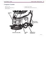
Page 97: ...Squeegee System 97 Service Manual SC450 Specifications Descriptions Model Advance SC450 20B Nilfisk SC450 53B SC450 53E Squeegee width 30 in 760 mm ...

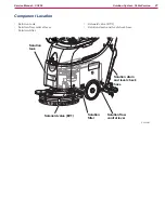
Page 98: ...n 98 Service Manual SC450 Wheel System Non Traction Component Location Front wheels on fixed axle Rear parking wheel Machine in parking position Machine in parking position Front wheels on fixed axle Rear parking wheel P200041 ...

Page 99: ...em Non Traction 99 Service Manual SC450 Specifications Descriptions Model Advance SC450 20B Nilfisk SC450 53B SC450 53E Diameter of wheels on fixed axle 10 in 254 mm Wheel pressure on the floor 710 psi 4 9 N mm2 ...

Reviews: