

108
34 - Scrub System, Cylindrical
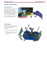
Removal and Installation
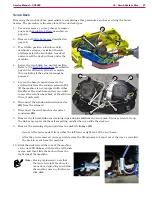
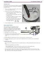
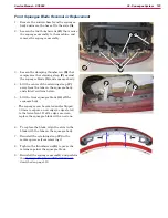
Scrub Deck Doors
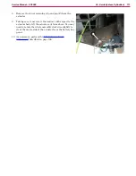
The scrub deck doors are removable for easier
access to any of the components under the
machine To prevent the doors from coming off
while the machine is in use, the hinges can’t be
separated unless the doors are open at least half
way
To remove the door, open it about 45 degrees and
lift it off the hinges
(A&B)
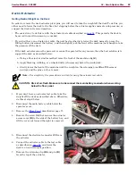
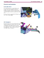
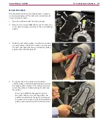
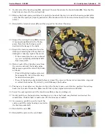
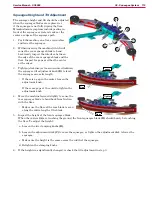
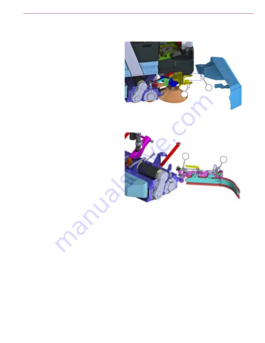
Side Squeegees
The side squeegees can be opened from the scrub
deck for maintenance or easier access to the deck
components, by pressing down on the release
lever
(A)
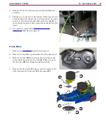
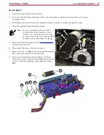
If you need to remove the side squeegee
for maintenance, remove the top and bottom
bolts
(B)
acting as a hinge pin
A
B
B
A