120
38 - Squeegee System
Actuator Limit Adjustment
The power module commands the actuator to raise
or lower, but the actuator itself determines when
it should stop moving This is accomplished by two
cam lobes and two micro switches (limit switches)
The lower cam is not adjustable, so the lower limit
is adjusted by rotating the leadscrew nut Then the
upper limit is adjusted by turning the cam lobe until
the actuator stops at the correct height
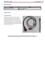
To make the adjustment, you will need to manually
power/control the actuator If you don’t have the
described on page 125, you can
use the Squeegee Lift Output Test described on
Just note that if you use the Output Test, you
may periodically cause a controller fault, and have to
reset the machine For simplicity, this procedure is
written for the test kit method
This procedure is typically performed as part of
replacing the actuator If the actuator is not already removed from the machine, then remove it following the
procedure on
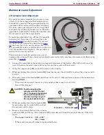
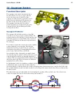
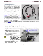
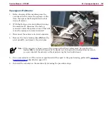
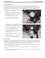
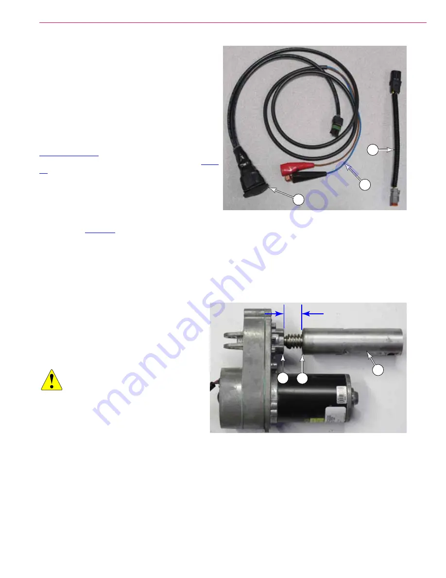
1 Connect the tester
(A)
to the positive and negative terminals of the battery
2 Using the adapter cable
(B)
, connect the tester to the actuator
3 While preventing the actuator leadnut
(E)
from turning, use the switch
(C)
, extend the actuator until it
stops
4 Measure the distance between the actuator
gearbox at
(G)
and the top of the leadnut at
(F)
5 Manually turn the leadnut until this
distance is 68mm (2.7”).
CAUTION: If while retracting the actuator
with the “Output Test”, it
appears the leadnut is going
to crash into the actuator
housing, let go of the leadnut
and let it spin.
6 While holding the leadnut from turning,
retract the actuator until it stops
7 Measure the retracted distance between
(G&F)
. The target is 23mm (.93”).
C
B
A
68mm Extended
23mm Retracted
E
G
F

