29
04 - Control System
Service Menu
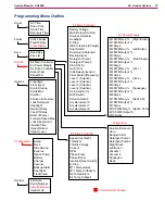
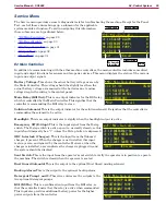
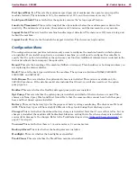
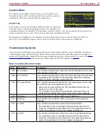
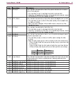
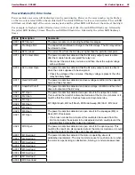
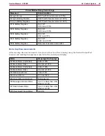
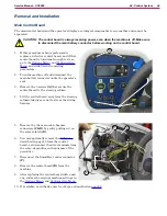
The Service menu provides access to diagnostic tools for troubleshooting the machine Except for the Panel
Test, each of these entries brings up a submenu for the applicable
system module or function To aid in navigating this information,
these submenus are hyperlinked below:
•
•
•
•
•
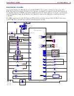
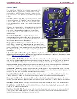
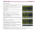
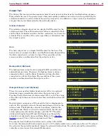
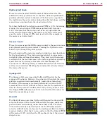
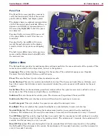
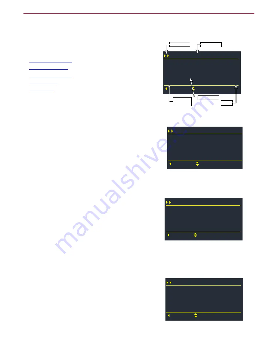
E2 Main Controller
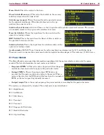
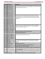
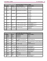
In addition to communicating with the other machine controllers, the main controller includes some direct
input and output functions for sensors and low-power devices This menu displays the status of the various
input and output signals
Battery Voltage:
This shows the actual battery voltage as seen by
the Main Controller This voltage should be slightly less than the
actual battery voltage as measured at the batteries due to minor
voltage drop in the wiring to the control panel
Main Relay (KSI Out):
This is an output indicator for the KSI relay,
which is controlled by the Main Controller. This signifies that the
controller is commanding the KSI relay to close
Solution Solenoid:
This is the output indicator for the solution solenoid. It signifies that the controller is
commanding the solenoid to be active
Headlight:
This is an output indicator to signify when the headlight output is active
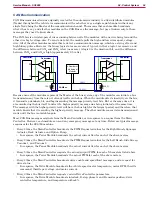
Emergency SW (E-Stop):
This is the input signal from the E-stop
switch The E-stop switch is active-open (i e normally closed), so this
input should normally be a “1” unless the E-stop button is depressed.
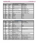
OBC Interlock (Charger):
This is the input from the Onboard
charger, if present When the charger is not installed, this input
is always zero, and ignored by the controller However, when the
charger is installed, a zero indicates the charger is plugged in, and
the system should be disabled
Seat Switch:
This is the input from the operator’s seat switch to verify the operator is in position to operate
the machine The switch is closed when the operator is seated
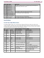
Dust Guard Solenoid:
This is the output to the optional Dust Guard misting solenoid
Backup Alarm:
This is the output to the optional backup alarm
Detergent Pump 1 and 2:
These two entries are the outputs to the
two optional detergent pumps
KSI (KSI In):
This is a confirmation input from the KSI relay, so
that the controller knows that the relay is active when commanded
This input also provides additional battery power for the higher
power outputs from the controller
E2 Main Controller
J1-14 BACKUP ALARM
Back
Scroll
M8 DETERGENT PUMP 1
M9 DETERGENT PUMP 2
J1-20 KSI
0
0
0
1
Value
Schematic
Identifier
Menu Level
Menu Name
Description
E2 Main Controller
J1-1 B+ (V)
Back
Scroll
J1-3 MAIN RELAY
J1-4 SOLUTION SOL
J1-9 HEADLIGHT
35.60
1
0
1
E2 Main Controller
J1-10 EMERGENCY SW
Back
Scroll
J1-11 OBC INTERLOCK
J1-12 SEAT SW
J1-13 DUST GUARD SOL
1
0
1
0
E2 Main Controller
J1-14 BACKUP ALARM
Back
Scroll
M8 DETERGENT PUMP 1
M9 DETERGENT PUMP 2
J1-20 KSI
0
0
0
1

