30
04 - Control System
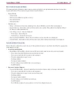
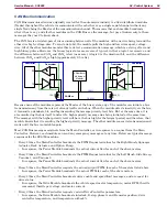
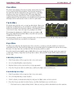
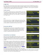
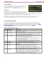
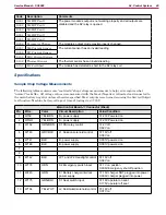
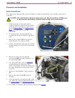
Horn (Out):
This is the output to the horn
Float Switch (Recovery):
This is the float switch in the recovery
tank that closes when the tank is full
Side Sweep (sensor):
This is the input from the proximity sensor
for the optional side broom When the side broom is in the up-
position, the sensor is active
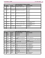
Solution Level Sensors 1, 2, 3, 4:
These are the 4 inputs from the solution tank level sensors The sensors
are normally closed, so they open as the solution level rises
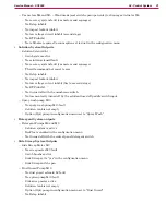
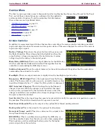
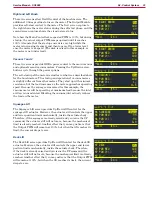
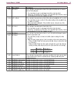
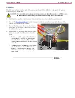
Horn Switch (In):
This is the input from the horn switch on the
operator’s steering column
BOP Switch:
This is the input from the Burst of Power switch on
the operator’s steering column
Solution Switch:
This is the input from the solution switch on the
operator’s steering column
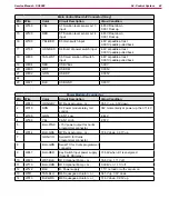
Accelerometer X, Y, Z:
These 3 inputs are from the machine’s accelerometers for X, Y, and Z directions
These are used to sense machine movement and also register machine impacts The units are 1/1000 G-force
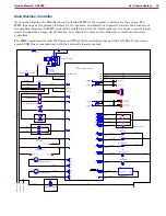
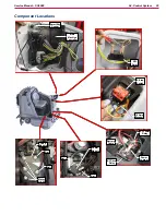
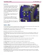
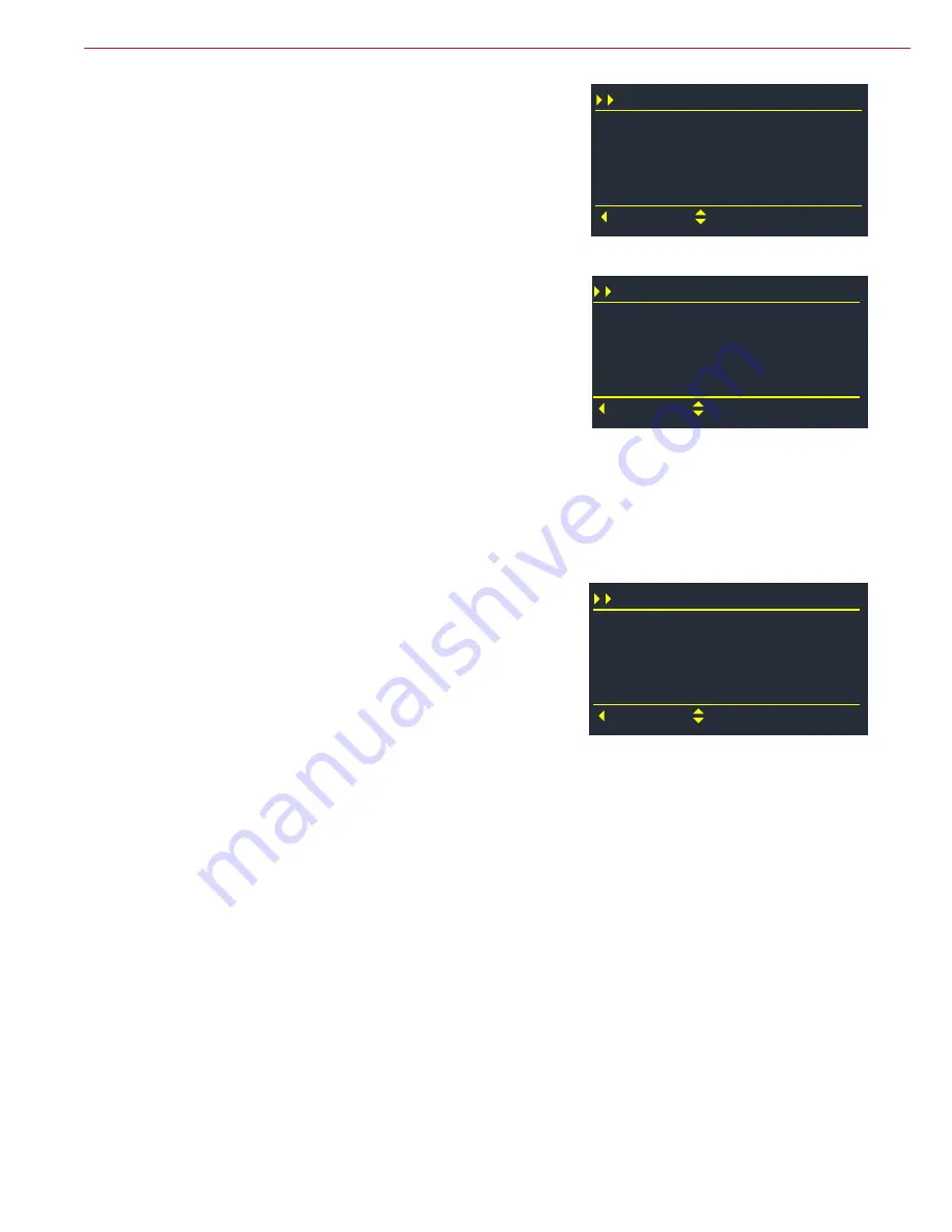
E3 Power Module
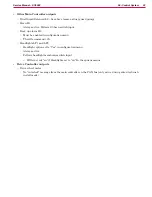
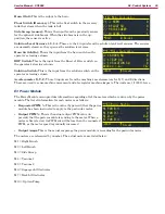
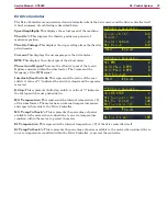
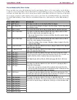
The Power Module menu provides information regarding all of the motors which are driven by the power
module. The list of information for each motor is as follows:
•
Requested PWM %:
This is the value (by percent) that the power
module has been instructed to apply to the particular motor
•
Output PWM %:
This is the actual output PWM value (in
percent) that the power module is sending to the motor When a
motor is first started, its PWM out will be less than the requested
PWM, as the motor speed is gradually increased
•
Output Amps:
This is the actual amperage the power module is recording for the particular motor
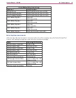
The motors are referenced by number. The actual motors are listed below:
M1 = Right Brush
M2 = Left Brush
M3 = Side Sweep
M4 = Vacuum 1
M5 = Vacuum 2
M6 = Squeegee Lift Actuator
M7 = Deck Lift Actuator
M10 = Option Pump
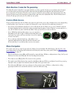
E2 Main Controller
J1-22 HORN
Back
Scroll
J2-8 FLOAT SW
J2-9 SIDE SWEEP
J2-10 LEVEL 1
0
0
1
1
E2 Main Controller
J2-16 HORN SW
Back
Scroll
J2-17 BOP SW
J2-18 SOLUTION SW
ACCEL-X (mG)
0
0
0
-762
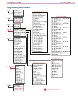
E3 Power Module
M1 PWM Req %
Back
Scroll
M1 PWM Out %
M1 Amps
M2 PWM Req %
0
0
0.0
0

