background image

FORM NO. 56041423 / SD 4317, SD 5120 - 4

GROUNDING INSTRUCTIONS

This appliance must be grounded. If it should electrically malfunction, grounding provides a path of least resistance for electric current to reduce the
risk of electric shock. This appliance is equipped with a cord having an equipment-grounding conductor and grounding plug. The plug must be plugged
into an appropriate outlet that is properly installed and grounded in accordance with all local codes and ordinances.

DANGER!

Improper connection of the equipment-grounding conductor can result in a risk of electric shock. Check with a qualified electrician or
service person if you are in doubt as to whether the outlet is properly grounded. Do not modify the plug provided with the appliance. If
it will not fit the outlet, have a proper outlet installed by a qualified electrician.

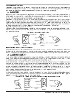
This appliance is for use on a nominal 120-volt circuit, and has a grounding plug that looks like the plug illustrated in Figure 1 below. A temporary adapter
illustrated in Figures 2 and 3 may be used to connect this plug to a 2-pole receptacle as shown in Figure 2 if a properly grounded outlet is not available.
The temporary adapter should be used only until a properly grounded outlet (Figure 1) can be installed by a qualified electrician. The green-colored
rigid ear, tab, or the like extending from the adapter must be connected to a permanent ground such as a properly grounded outlet box cover. Whenever
the adapter is used, it must be held in place by a metal screw.  Grounding adapters are not approved for use in Canada.
Replace the plug if the grounding pin is damaged or broken.
The Green (or Green/Yellow) wire in the cord is the grounding wire.  When replacing a plug, this wire must be attached to the grounding pin only.
Extension cords connected to this machine should be 12 gauge, three-wire cords with three-prong plugs and outlets.  DO NOT use extension cords
more than 50 feet (15 m) long.

PLEASE NOTE:  FOR NORTH AMERICA ONLY

INSTRUCTIONS VISANT LA MISE À LA TERRE

Cet appareil doit être mis à la terre. En cas de défaillance ou de panne éventuelles, la mise a la terre fournit au courant un chemin de moindre résistance
qui réduit le risque de choc électrique. Cet appareil est pourvu d’un cordon muni d’un conducteur de terre et d’une fiche avec broche de terre. La fiche
doit être branchée dans une prise appropriee correctement installée et mise à la terre conformément aux règlements et ordonnances municipaux.

AVERTISSEMENT !

Un conducteur de terre mal raccordé peut entraîner un risque de choc électrique. Consulter un électricien ou un technicien d’entretien
qualifié si vous n’êtes pas certain que la prise est correctement mise à la terre. Ne pas modifier la fiche fournie avec l’appareil - si elle
ne peut être insérée dans la prise, faire installer une prise adéquate par un électricien qualifié.

Cet appareil est destiné à un circuit de 120 V et est muni d’une fiche de terre semblable à celle illustrée par le croquis 1.  Un adaptateur temporaire
semblable à celui illustré par le croquis 2 et C peut être utilisé pour brancher cette fiche à une prise bipolaire comme l’illustre le croquis 2 si une prise
avec mise à la terre n’est pas disponible. L’adaptateur temporaire devrait etre utilisé seulement jusqu’à ce qu’une prise avec mise à la terre soit installée
par un électricien qualifié. L’oreille rigide ou le crochet ou autre dispositif semblable, de couleur verte, prolongeant l’adaptateur doit Iêtre raccordé
à un élément correctement mis à la terre comme le couvercle d’une boîte de sortie mise à la terre. L’adaptateur doit être fixé par une vis métallique.
Note: Au Canada, I’utilisation d’un adaptateur temporaire n’est pas autorisée par le 

Code


canadien de l’électricité.

Remplacez la prise si la prise de terre est abîmée ou cassée.
Le fil Vert (ou Vert/Jaune) dans la ganse est le fil de terre. Lors du remplacement d´une prise, ce fil doit être raccordé à la prise de terre uniquement.
Les ralonges connectées à cette machine doivent avoir 12 mesures, trois ganses de fil ayant trois fiches masculines féminines tree-prong plugs
and outlets.
 N´UTILISEZ PAS de ralonge de plus de 15 m (50 pieds) de long.

VEUILLEZ NOTER:  CES INSTRUCTIONS CONCERNENT UNIQUEMENT L’AMÉRIQUE DU NORD

Summary of Contents for SD 4317

Page 1: ...11 98 revised 10 02 Form Number 56041423 SD 4317 SD 5120 OPERATOR MANUAL AND PARTS LIST Advance MODELS 56201631 56201632 ...

Page 2: ...NTES CONSIGNES DE SÉCURITÉ 3 GROUNDING INSTRUCTIONS 4 INSTRUCTIONS VISANT LA MISE À LA TERRE 4 Introduction 5 Know Your Machine 5 Installing the Brush or Pad Holder 5 Operation 5 After Use 6 Troubleshooting 6 Technical Specifications 6 Handle System 7 8 Base System Wiring Diagram 9 10 Solution Tank Kit Optional 11 12 ...

Page 3: ...ttachments Donotusewithdamagedcordorplug Ifapplianceisnotworkingasitshould hasbeendropped damaged leftoutdoors ordropped into water return it to a service center Do not pull or carry by cord use cord as a handle close a door on a cord or pull cord around sharp edges or corners Do not run appliance over cord Keep cord away from heated surfaces Do not unplug by pulling on cord To unplug grasp the pl...

Page 4: ...ourner l appareil à un atelier de réparation s il ne fonctionne pas bien s il est tombé ou s il a été endommagé oublié à l extérieur ou immergé Ne pas tirer soulever ou traîner l appareil par le cordon Ne pas utiliser le cordon comme une poignée le coincer dans l embrasure d uneporteoul appuyercontredesarêtesvivesoudescoins Nepasfaireroulerl appareilsurlecordon Garderlecordon àl écart des surfaces...

Page 5: ...têtremisàlaterre Encasdedéfaillanceoudepanneéventuelles lamisealaterrefournitaucourantunchemindemoindrerésistance qui réduit le risque de choc électrique Cet appareil est pourvu d un cordon muni d un conducteur de terre et d une fiche avec broche de terre La fiche doit être branchée dans une prise appropriee correctement installée et mise à la terre conformément aux règlements et ordonnances munic...

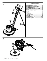
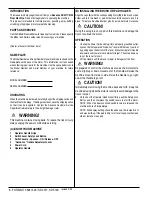
Page 6: ...er 5 Power Cord 6 Operator Handle B INSTALLING THE BRUSH OR PAD HOLDER Align the Lugs A with the corresponding Slots B in the brush or pad holder and turn the brush or pad holder counterclockwise to lock it in place To remove brush pad holder give it a quick hard turn clockwise CAUTION Using the wrong brush or pad on this machine can damage the floor or overload the motor OPERATION 1 Unwrap the Po...

Page 7: ...the job CIRCLES ON THE FLOOR Machine standing still while the brush or pad is running FLOOR FINISH REMOVED Improper pad too aggressive Solution too strong MACHINE WOBBLES DURING OPERATION Defective pad one side is more dense than the other Machine left sitting on brush or pad for extended period of time causing bristles or pad to take a set Pad not seated properly into pad holder bristles Warped b...

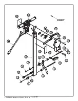
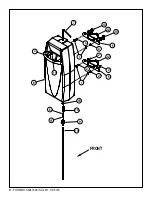
Page 8: ...7 FORM NO 56041423 SD 4317 SD 5120 revised 10 02 FRONT 1 1 2 2 3 13 14 5 7 8 9 9 22 4 17 4 6 20 16 19 18 21 15 12 11 23 25 26 ...

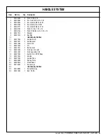
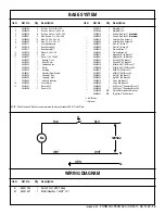
Page 9: ...sh Flt Harden 40 x 1 00 x 16 8 56201015 1 Bracket 9 56201016 2 Bushing 10 Intentionally Omitted 11 56201026 1 Handle Cover 12 56201027 2 Handle Lever 13 56201028 1 Latch Arm 14 56201029 1 Pin 15 56201031 1 Button Lock 16 56201032 1 Cord Set 14 3 x 50 17 56201033 1 Cord Assembly 14 3 18 56201034 1 Switch N O SPST Snap 19 56201054 1 Handle 20 56201056 1 Handle Tube 21 56263648 1 Spring Plate 22 5638...

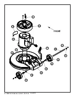
Page 10: ...9 FORM NO 56041423 SD 4317 SD 5120 1 FRONT 12 11 10 9 8 7 2 4 6 4 6 5 3 5 13 revised 2 00 ...

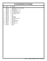
Page 11: ...ight Kit 17 56201062 1 Weight Kit 20 56505910 1 Pad Holder Assy 17 standard 56505920 1 Pad Holder Assy 20 standard 56505270 1 Level Set Pad Holder 17 56505280 1 Level Set Pad Holder 20 56505915 1 ProLite Brush 17 56505925 1 ProLite Brush 20 56505914 1 Prolene Brush 17 56505924 1 Prolene Brush 20 56505911 1 MagnaGrit 46 Brush 17 56505921 1 MagnaGrit 46 Brush 20 56505912 1 DynaGrit 80 Brush 17 56505...

Page 12: ...11 FORM NO 56041423 SD 4317 SD 5120 FRONT 1 1 2 2 2 2 3 4 4 5 5 6 15 9 10 14 16 8 11 7 13 13 12 12 ...

Page 13: ... SAE 5 16 2 56002826 4 Nut Hex Nyl Loc Thin 5 16 18 3 56002884 4 Scr Hex Hd SS 5 16 18 x 1 25 4 56009217 2 Nut Hex Flange Loc 5 16 5 56201005 2 Strap 6 56201007 1 Plug 7 56201008 1 Handle Valve 8 56201020 1 Tank Solution 9 56201035 1 Barb Adapter 3 8 x 3 4 NPT 10 56201036 1 Hose PVC 11 56201047 4 Wsh Sealing SS 5 16 12 56352829 2 Clamp Hose SAE 52 13 56370711 2 Nut Thumb 14 56379170 1 Spring Compr...

Page 14: ...Nilfisk Advance Inc 14600 21st Avenue North Plymouth MN 55447 3408 www nilfisk advance com Phone 800 989 2235 Fax 800 989 6566 2002 Nilfisk Advance Inc Plymouth MN 55447 3408 Printed in the U S A ...

Reviews: