background image

56041481

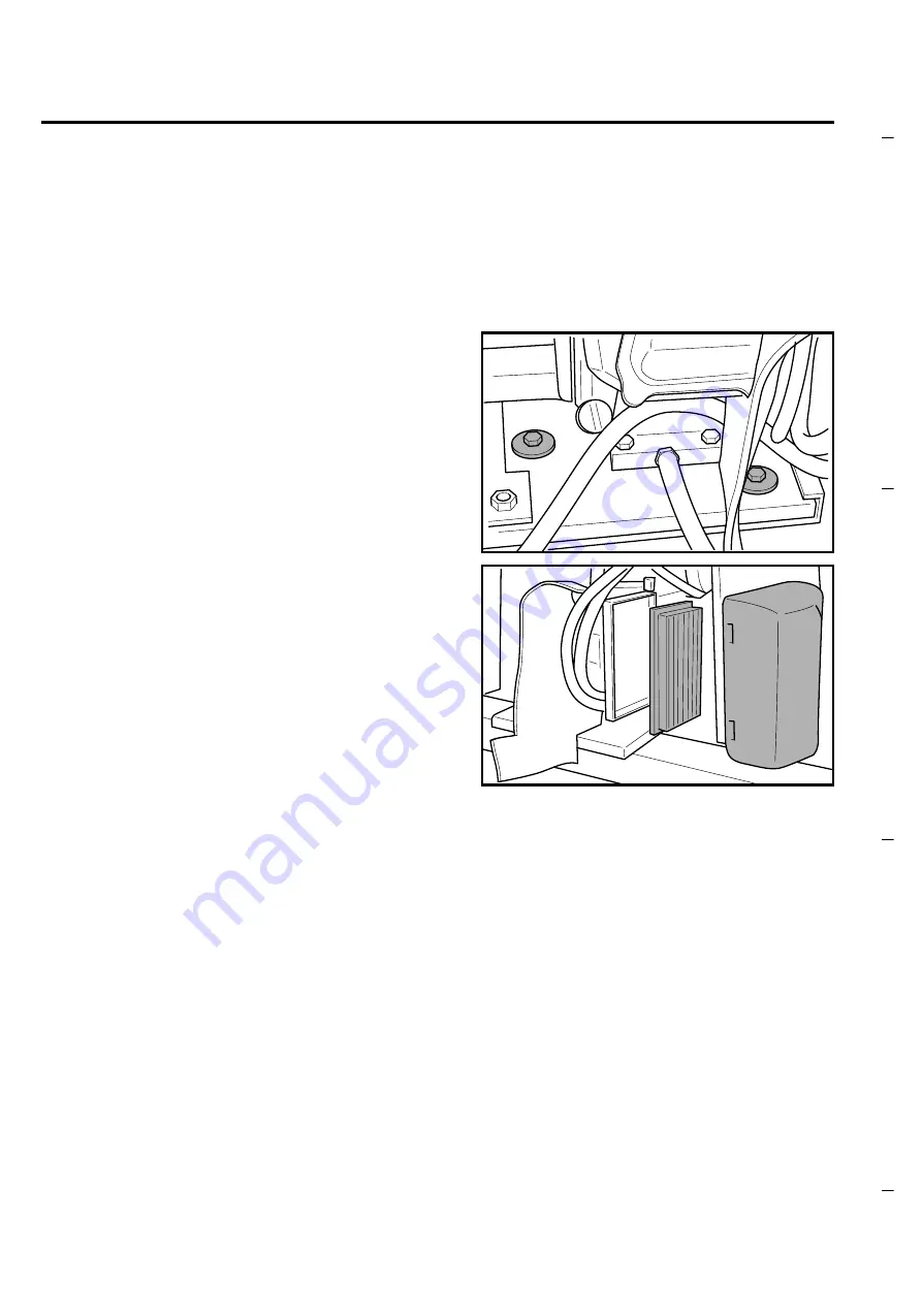
Clean or replace the air filter according to the 
instructions of the engine Manual or whenever it is 
necessary.

In order to get access to the air filter the engine 
assembly must be slid out; to slide out the engine 
assembly first the right side wall of the machine must 
be removed (see engine oil replacement procedure for 
right side wall removal).

Then two screws must be loosened (17 mm wrench 
required) to allow to slide out the engine plate/
assembly

Now the engine air filter can be reached (save two 
screws).

MAINTENANCE

24

Summary of Contents for SR 1300 B

Page 1: ... 9312 or 800 331 3339 MI OH IN only 2011 N High St Lansing Michigan 48906 Fax 517 484 9836 Email CustServ Michco com Web site www Michco Com Parts Web site www FloorMachineParts Com Order Parts on Line at www FloorMachineParts Com Directly to Parts Service By Email Shop Michco com By Fax 517 702 2041 By Voice Use numbers above Serving the Cleaning Industry Since 1922 Notice All copyrighted materia...

Page 2: ...FORM No 56041481 1 00 03 SR 1300 B ECO OPERATOR MANUAL Advance MODELS 908 3013 010 908 3301 010 ...

Page 3: ...PERFORMANCES OF THE MACHINE WITH GASOLINE ENGINE 15 SIDE BRUSHES ADJUSTMENT AND REPLACEMENT 16 MAIN BRUSH REPLACEMENT 17 18 FILTER CLEANING AND REPLACEMENT 19 20 MAINTENANCE 21 BATTERIES CONTROL AND RECHARGE 21 BRAKES ADJUSTMENT 22 FRONT LAMP REPLACEMENT 22 MAINTENANCE OF THE GASOLINE ENGINE 23 24 SUMMARY OF MAINTENANCE CONTROLS battery version 25 SUMMARY OF MAINTENANCE CONTROLS gasoline version 2...

Page 4: ...en machine operating malfunctions occur make sure that they are not caused by a lack of routine maintenance If not request assistance from the service centre If parts must be replaced request ORIGINAL spare parts from a dealer and or Authorised Retailer For all maintenance operations disconnect the electric power supply to the machine Do not remove the guards which require the use of tools to be d...

Page 5: ...ems be supplied with the machine 1 envelope with cables for batteries and connector for battery charger 2 technical documents Spare Parts Catalogue Manual for Use and Maintenance and for the gasoline version only Use and Maintenance Manual of the engine 2 ...

Page 6: ...3 km h 2 6 mil h 3 5 km h 2 2 mil h Max slope 20 20 Main brush Ø 300 x 800 mm 11 8 x 31 4 in Ø 300 mm x 800 mm 11 8 x 31 4 in Side brush Ø 460 mm 18 11 in Ø 460 mm 18 11 in Cleaning width with 1 side brush 1012 mm 40 in 1012 mm 40 in Cleaning width with 2 side brushes 1251 mm 49 in 1251 mm 49 in Front wheel nr 1 Ø 300 mm 12 in Ø 300 mm 12 in Rear drive wheels nr 2 Ø 300 mm 12 in Ø 300 mm 12 in Dir...

Page 7: ...d adjustment of the side brushes 7 Indicator of the operation of left right side brushes 8 ON button of filter shaker motor 9 Emergency stop push button 4 10 ON OFF main key switch 11 Start Stop push button for gasoline engine 12 Selection of forw reverse speed light ON OFF horn 13 Steering wheel 14 Pedal for flap lifting 15 Brake pedal 16 Accelerator 17 Parking brake lever 18 Lever for left side ...

Page 8: ...he compartment lid toward the steering wheel and verify which one of the three possibilities is applied to your machine If the batteries are installed open one of the caps of every battery and check if they are filled with electrolyte 1 If the battery is filled 1a Check the electrolyte level in every cell and if necessary fill up with distilled water 1b Proceed with a battery recharge according to...

Page 9: ...lower than 1 270 Kg when at 25 C according to the instructions specified below and in the Battery User Manual BATTERY FILLING UP WITH ACID SOLUTION Warning the battery acid is corrosive if it comes in contact with the skin or eyes rinse thoroughly with water and consult a physician The batteries must be filled in a well ventilated area Fill every battery cell with acid the right level is specified...

Page 10: ...th the machine can be used for the connection of the batteries WARNING before starting the recharge the battery connector must be disconnected from the machine If the machine is equipped with a gasoline engine gasoline version fill the fuel tank with unleaded gasoline Check the engine oil level see the chapter MAINTENANCE Climb onto the machine and adjust the seat to find the most comfortable posi...

Page 11: ...start the job in battery mode If the machine is equipped with the gasoline engine proceed with the start of the engine itself START STOP OF THE GASOLINE ENGINE To start the gasoline engine press the red button shown in the figure to stop the engine press the same button again Displayed datum function Display reading 1 Voltmeter the battery voltage is normally shown on the display A block function ...

Page 12: ...h the suction motor indicator The temporary activation of the main brush and suction electrical motors will also occur the relevant light indicators will flash Note the working parameters of programs P1 and P2 are pre set by the manufacturer of the machine if you want to change the pre set values call the customer service personnel of your supplier Lower the side brush es pressing the top of the r...

Page 13: ...seconds Auto Power Off except the gasoline engine the light indicators of the selected working program and of the suction fan will start flashing The automatic restart of all functions will automatically occur as soon as the accelerator pedal will be pushed again Auto Power ON In order to enable the selection of a different working program first disable the previously selected one When it is neces...

Page 14: ...b the automatic filter sheaking will occur every five minutes To collect light and bulky waste materials lift the front flap using the left pedal do not press the pedal down for a long time not to reduce the suction capability of the machine The machine get an automatic breaking function when the accelerator pedal is released when necessary the service brake can also be used see the figure When dr...

Page 15: ...ure Before leaving the machine make sure that the side brush es be lifted the parking brake engaged and the master key in the Off position counter clockwise At the end of the job or whenever it is necessary empty the rear dirt container WARNING Be sure not to be near to any person and not to cause any damage or accident For safety reasons the dirt tank control lever can be operated only if at the ...

Page 16: ...ank move the lever rearward as shown in the figure Approach the rubbish bin Release the lever that places itself centrally push it on the outside until the tank door is opened to allow the discharge of the picked up material 13 ...

Page 17: ...an for the moves necessary to approach move away to from the rubbish bin Make sure the Hopper Safety Support is in place whenever attempting to do any maintenance work under or near the raised hopper Lift the hopper to its maximum height by pressing the red safety button and moving the JOY STICK put the safety device in the holding position and lower the hopper enough to lock it Lift the hopper us...

Page 18: ...ours of the batteries installed on the machine on the intensity of the selected working program on the charge status of the batteries On this machine in order to guarantee the reliability of the batteries two safety features are envisaged 1 protection against the deep discharge of the battery when the battery voltage drops down to about 20 Volt the automatic stop of all function will occur except ...

Page 19: ...nd verify that the contact with the floor is as shown in the figure If necessary repeat the adjustment sequence When the brush is remarkably worn out it is necessary to replace it Just press the two tabs inwards and remove the brush Reinstall the new brush by carring out the reverse operation press the brush with your hands Note when the brush is replaced set the adjusting devices to their origina...

Page 20: ...ain brush is automatically adjusted no need of manual adjustment The complete wear of the main brush and then the need to replace it is notified with code 800 on the display Please meet the following procedure for the main brush replacement Open the side door on the right side of the machine unscrewing the knob shown in the figure Remove the three knobs used to fix the lid of the main brush compar...

Page 21: ...h pay attention to the correct angle of the brush bristles look at the next figure Fit the new brush in its compartment paying attention to the engagement of the plastic adapter with the hub on the opposite side of the compartment Fit the lid of the main brush compartment using the three knobs previously removed MAIN BRUSH REPLACEMENT 18 ...

Page 22: ...tric cable of the filter shaker motor and suction fan the machine must first be turned off and the key out Loosen the locking nuts on the two knobs and remove the knobs Remove the support of the suction fan Remove the the panel filter Clean the filter shaking it and blowing with compressed air pressure not higher than 6 bar from the side where the metal protection net is mounted to prevent damage ...

Page 23: ...en the two knobs and locking nuts and reconnect the electric cable If the filter is damaged or can not be properly cleaned replace it with a new one Ask to your supplier for the new spare part Polyester washable filters are also available FILTER CLEANING AND REPLACEMENT 20 ...

Page 24: ... eyes rinse thoroughly with water and consult a physician When necessary proceed with a recharge of the battery according to the following instructions and taking also into account what is specified in the Battery User Manual switch the machine Off and remove the master key Warning before starting the recharge the battery connector must be disconnected from the machine the recharge must be done in...

Page 25: ... some adjustments can be done on the rear wheels loosen the locking nut A turn adjuster B tighten locking nut A FRONT LAMP REPLACEMENT In order to replace the front lamp remove the transparent cover replace the lamp paying attention to the volt and watt ratings fit the transparent cover MAINTENANCE 22 A B ...

Page 26: ... access the forth and fifth screws Warning the engine oil must be replaced the first time after 50 working hours the succeeding times it must be replaced every 100 hours NOTE the engine is equipped with an oil safety device this device does not allow the engine start or will automatically stop the engine in the event that the oil level be too low No monitor LED is provided for this safety device U...

Page 27: ...e engine assembly must be slid out to slide out the engine assembly first the right side wall of the machine must be removed see engine oil replacement procedure for right side wall removal Then two screws must be loosened 17 mm wrench required to allow to slide out the engine plate assembly Now the engine air filter can be reached save two screws MAINTENANCE 24 ...

Page 28: ... is submitted to a self discharge phenomenon In the event that the machine is not used for a long time e g 3 or 4 weeks it is necessary TO RECHARGE THE BATTERY infact the battery voltage MUST NEVER drop down below 20 Volt 25 CONTROL UPON DELIVERY EVERY 30 HOURS EVERY 50 HOURS EVERY 100 HOURS EVERY 400 HOURS Battery liquid level and voltage check OR EVERY TWO WEEKS Check the carbon brushes of all e...

Page 29: ...e g 3 or 4 weeks it is necessary TO RECHARGE THE BATTERY infact the battery voltage MUST NEVER drop down below 20 Volt SUMMARY OF MAINTENANCE CONTROLS gasoline version 26 3350 engine shaft RPM with no function working and battery voltage at about 24 5 Volt CONTROL UPON DELIVERY TWO TIMES PER WEEK ONE TIME PER WEEK EVERY 50 HOURS EVERY 50 HOURS EVERY 100 HOURS EVERY 400 HOURS Battery liquid level a...

Page 30: ...High capacity batteries for machine without gasoline engine Battery charger Different types of main bushes and side brushes Polyester panel filter it can be washed In order to have more detailed information for all the optional items get in touch with your supplier of the machine 27 ...

Page 31: ... rear drive wheels 302 The machine does not start or in the event it was working will stop Possible problem with traction control electronic circuit or fuse Turn the machine off and wait 5 seconds Turn the machine on If code 302 will remain call service 305 The machine functions will stop High temperature on the electronic control circuits 95 C If the ambient temperature is high let the machine co...

Page 32: ...ION Milan Italy COD 56041481 0 00 03 Nilfisk Advance Inc 14600 21st Avenue North Plymouth MN 55447 3408 www nilfisk advance com Phone 800 989 2235 Fax 800 989 6566 1999 Nilfisk Advance Inc Plymouth MN 55447 3408 Printed in the U S A ...

Reviews: