background image

TÜRKÇE / B-21

FORM NO. 56041749 - SR 2000 - 

B-21

TEKN

İ

K ÖZELL

İ

KLER (ünite üzerinde monte ve test edilen)

Model 


SR 2000 VD LPG


SR 2000 VD Petrol


SR 2000 VD Dizel

Model No. 


56516755


56516750


56516753

Ses Bas

ı

nc

ı

 Seviyesi

IEC 60335-2-72: 2002 De

ğ

i

ş

ikli

ğ

i. 1:2005, ISO 11201) 

dB (A) 

92.3

Ses Gücü Seviyesi
IEC 60335-2-72: 2002 De

ğ

i

ş

ikli

ğ

i. 1:2005, ISO 3744) 

dB (A) 

Lwa 112,1

Toplam A

ğ

ı

rl

ı

lbs/kg 

3800 / 1724

El Kontrollerindeki Titre

ş

imler (ISO 5349-1) 

m/s

0,93 m/s

2

Koltuktaki Titre

ş

imler (EN 1032) 

m/s

0,54 m/s

2

T

ı

rmanma  

21% 

(11.8°)
Summary of Contents for SR 2000

Page 1: ...A English B Türkçe SR 2000 Kullanim Talimatlari Instructions for Use 10 08 FORM NO 56041749 Printed in USA Nilfisk Models Models 56516750 Gas 56516755 LPG 56516753 Diesel ...

Page 2: ... A 8 BACKUP ALARM OPTION A 8 SEAT ADJUSTMENT A 8 PARKING BRAKE A 8 CIRCUIT BREAKERS A 9 GLOW PLUG DIESEL A 9 HOPPER LIFT SIDE BROOM LEVER A 9 HOPPER DUMP RETURN CONTROL LEVER A 9 THROTTLE CONTROL A 10 CHECK ENGINE LIGHT A 10 LEFT SIDE BROOM LIFT AND POWER CONTROL OPTION A 10 MAIN BROOM LIFT A 10 WORK LIGHT SWITCH OPTION A 11 LIGHT SWITCH OPTION A 11 HORN BUTTON A 11 CAB OPTION NOT SHOWN A 11 LOW O...

Page 3: ...cking company that delivered the machine Contact the trucking company immediately to file a freight damage claim MACHINE OPERATION YOUR SWEEPER HAS BEEN SHIPPED COMPLETE BUT DO NOT ATTEMPT TO OPERATE WITHOUT READING THE FOLLOWING INSTRUCTIONS 1 Uncrate the machine and carefully remove from skid to prevent damage 2 Connect and tighten battery cables 3 Fill tank with UNLEADED gasoline or Diesel Fuel...

Page 4: ...must be level horizontal Operate only when lids doors and access panels are securely closed Never travel with the hopper in the raised position Watch out for obstructions especially overhead Carry no passengers on the machine Report damage or faulty operation immediately Do not operate the machine until repairs have been completed Maintenance and repairs must be done by authorized personnel only N...

Page 5: ... Figure 2 This meter B is located to the left of the oil pressure gauge on the instrument console This meter is activated when the engine begins running The meter indicates actual run time of the machine The meter can be used to indicate when maintenance should be done to the machine FUEL GAUGE See Figure 2 The fuel gauge C is located between the water temperature gauge and the volt meter on the i...

Page 6: ...ter shaker motors for 20 to 30 seconds after it has been pushed When the shaker motors have been activated the brooms and impeller fan will stop The shaker motors will only operate with the hopper in the SWEEP position HYDRAULIC FLUID SIGHT GLASS See Figure 3 The sight glass is located on the side of the hydraulic oil reservoir The sight glass indicates the level of the hydraulic oil in the reserv...

Page 7: ... position is a momentary position The key will revert to the IGN ON position when it is released WET SWEEP BYPASS SWITCH OPTION See Figure 2 The wet sweep bypass switch I is located to the right of the steering wheel under the shaker motor switch The switch activated will shut off the vacuum motor This will keep the dust filters from being ruined by the water pickup from sweeping water 4 WAY TURN ...

Page 8: ...peed 5 To stop the machine put light foot pressure on the opposite end of the accelerator and directional control pedal If the machine is moving forward put light foot pressure on the lower portion of the pedal If the machine is moving in reverse put light foot pressure on the upper portion of the pedal BACK UP ALARM OPTION See Figure 2 The back up alarm N is operated by a switch that is located u...

Page 9: ...fired until it is running smoothly HOPPER LIFT SIDE BROOM LEVER See Figure 9 The Hopper Lift Side Broom lever R is located to the left side of the drive compartment The lever is a three position control that operates the hopper lift side broom and optional left side broom NOTE The hopper lift lever will not function until the hopper has been rotated to clear the body of the sweeper The lever is sp...

Page 10: ...ow to diagnose the problem LEFT SIDE BROOM LIFT AND POWER CONTROL OPTION See Figure 10 The left side broom lift control V is located on the left side of the instrument panel To raise and stop the side broom grasp the lever and push the lever to the locking notch with the UP mark To lower the side broom grasp the lever and push it up to the right away from the locking notch Let the lever lower unti...

Page 11: ... Lights Side Broom Lights Instrument Lights All gauges with the exception of the hour meter can have an option internal instrument light HORN BUTTON See Figure 2 The horn button Z is located to the left of the steering column The horn button is always active Push the horn button to sound the horn CAB OPTION The all weather cab is available for this machine along with several cab only options Winds...

Page 12: ...ree of debris which will inhibit rotation pick up NOTE Always wear hand protection when cleaning debris from brooms and or brushes 2 Check squeegees to make sure there is no damage and they meet the floor TO OPERATE SWEEPER Make sure parking brake is released 1 Lower the side and main broom to the floor The main broom control may be placed in either the FLOAT or SWEEP position 2 Turn Broom Fan Swi...

Page 13: ... into main aisle B ahead of time Do an entire floor or section at one time 2 Pick up oversize debris before sweeping 3 Don t turn steering wheel too sharply when machine is in motion The machine is very responsive to movement of the steering wheel so avoid sudden turns 4 Try to follow as straight a path as possible Avoid bumping into posts or scraping the sides of the machine 5 When placing the ma...

Page 14: ...MP position The hopper will begin to rotate 3 Once the hopper rotation speed doubles the hopper lift lever R will work Raise the hopper to the desired level MINIMUM OF 8 or 20 cm OF LIFT REQUIRED by pulling back the hopper lift lever R to the RAISE position 4 Drive forward 12 to 18 inches slowly with the hopper up before completing the dump cycle 5 Push the hopper rotation and dump lever S to the ...

Page 15: ... to exceed 100 P S I or cleaned with soap and water Do not attempt to use Filter Panels that have not dried completely THE DUST CONTROL SYSTEM The baffle system that is built into the debris hopper is designed minimize dust in the air while the machine is sweeping The debris from sweeping is thrown into the hopper The impeller vacuum fan pulls the lighter dust up and through a baffle system The Pr...

Page 16: ...ber door 10 A Start the engine 11 Put the broom lever in the SWEEP position 12 Let the broom sweep in place for 30 seconds 13 Put the broom lever in the UP position 14 Back the machine off the test spot 15 Inspect the polished area where the broom swept for broom bristle contact with the floor The area of broom bristle contact with the floor should be 2 to 3 16 inches or 5 to 8 cm wide MAIN BROOM ...

Page 17: ...e the broom motor assembly into a position so that the broom contacts the floor at a 3 degree angle when lowered SIDE BROOM REPLACEMENT Put the side broom lift control in the UP position Remove the retaining screw in the bottom middle of the side broom Remove the side broom Transfer the side broom flange spacer screws washers and nuts to the replacement side broom Put the replacement side broom on...

Page 18: ...y 100 hours of machine use Lubricate drive wheel swivel bearing 2 B and the front wheel bearings C with a good multi purpose grease The steering gear assembly has a grease fitting located on the front section of the steering gear housing Use E P Lithium grease to 3 lubricate the steering gear through the grease fitting Lubricate all other moving joints 4 D of the machine with 10 oil Lubricate the ...

Page 19: ...ENGLISH A 19 FORM NO 56041749 SR 2000 A 19 GENERAL MACHINE MAINTENANCE ...

Page 20: ...main brush end to end 19 Clean or replace panel filter Perform recommended engine maintenance See engine manual EVERY 100 HOURS 20 Change crankcase oil 21 Change engine oil filter 22 Lubricate drive wheel swivel bearing 23 Lubricate front wheel bearings 24 Lubricate steering gear box 25 Lubricate all moving joints 26 Check brake pads for wear and adjust accordingly 27 Lubricate clamp ends of the t...

Page 21: ...0 VD Diesel Model No 56516755 56516750 56516753 Sound Pressure Level IEC 60335 2 72 2002 Amend 1 2005 ISO 11201 dB A 92 3 Sound Power Level IEC 60335 2 72 2002 Amend 1 2005 ISO 3744 dB A Lwa 112 1 Total Weight lbs kg 3800 1724 Vibrations at the Hand Controls ISO 5349 1 m s2 0 93 m s2 Vibrations at the Seat EN 1032 m s2 0 54 m s2 Gradeability 21 11 8 ...

Page 22: ... 8 KOLTUK AYARI B 8 PARK FRENİ B 8 DEVRE KESİCİLER B 9 ISITMA BUJİSİ Dizel B 9 HUNİ KALDIRMA YAN SÜPÜRGE KALDIRMA KOLU B 9 HUNİ BOŞALTMA DÖNÜŞ KONTROL KALDIRMA KOLU B 9 GAZ KONTROLÜ B 10 MOTOR KONTROL IŞIĞI B 10 SOL YAN SÜPÜRGE KALDIRMA VE GÜÇ KONTROLÜ OPSİYON B 10 ANA SÜPÜRGE KALDIRMA B 10 ÇALIŞMA IŞIĞI ANAHTARI OPSİYON B 11 IŞIK ANAHTARI OPSİYON B 11 KORNA DÜĞMESİ B 11 KABİN OPSİYON GÖSTERİLMİYO...

Page 23: ...lebilmesi için sevkıyat sandığının tüm parçalarını saklayın Tespit edilen navlun hasarını bildirmek üzere derhal taşıma şirketi ile irtibata geçin MAKİNEYİ ÇALIŞTIRMA TEMİZLEYİCİNİZ KOMPLE HALDE SEVK EDİLMİŞTİR ANCAK AŞAĞIDAKİ TALİMATLARI OKUMADAN MAKİNEYİ KULLANMAYA ÇALIŞMAYIN 1 Makineyi sandıktan çıkarın ve hasarı önlemek için dikkatlice paletten indirin 2 Batarya kablolarını takın ve sıkın 3 De...

Page 24: ...altmayın Huniyi eğimli bir yerdeyken rampa boşaltmayın Makine düz seviyede yatay olmalıdır Yalnızca kapaklar kapılar ve erişim panelleri sıkıca kapalıyken çalıştırın Asla huni kaldırılmış konumdayken gezmeyin Özellikle üst tarafta tıkanıklıklara dikkat edin Makinede yolcu taşımayın Hasar ya da hatalı kullanımı hemen bildirin Tamirat tamamlanmadan makineyi çalıştırmayın Bakım ve tamir işlemleri sad...

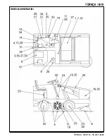
Page 25: ...suyu sıcaklığını Fahrenheit biriminde gösterir SAAT ÖLÇER Bkz Şekil 2 Bu gösterge B gösterge konsolunun üzerinde yağ basıncı göstergesinin solunda bulunmaktadır Bu sayaç motor çalışmaya başladığında etkinleşir Saat ölçer motorun kaç saat çalıştığını gösterir Makinede bakımın ne zaman yapılacağını belirlemek için bu saat ölçer kullanılabilir YAKIT GÖSTERGESİ Bkz Şekil 2 Yakıt göstergesi C gösterge ...

Page 26: ...re sallama motorlarını 20 30 saniyeliğine etkinleştiren anlık bir anahtardır Sallama motorları etkinleştirildiğinde süpürgeler ve pervane fanı durur Sallama motorları sadece huni SÜPÜRME konumundayken çalışacaktır HİDROLİK SIVISI GÖZETLEME CAMI Bkz Şekil 3 Gözetleme camı hidrolik yağı haznesinin yan tarafındadır Gözetleme camı haznedeki hidrolik yağı seviyesini gösterir Huni aşağı konumdayken göze...

Page 27: ...r çalıştırılır Bu anlık bir konumdur Anahtar bırakıldığında IGN ON konumuna geri dönecektir ISLAK SÜPÜRME BYPASS ANAHTARI OPSİYON Bkz Şekil 2 Islak süpürme bypass anahtarı I direksiyonun sağında sallama motoru anahtarının altındadır Anahtar etkinleştirildiğinde vakum motoru kapanır Böylece süpürge suyundan geri alınan su nedeniyle toz filtrelerinin bozulması önlenir 4 YÖNLÜ DÖNÜŞ SİNYALLERİ OPSİYO...

Page 28: ... ayak basıncını arttırın 5 Makineyi durdurmak için gaz pedalının ve yön kontrol pedalının karşı ucuna hafif ayak basıncı uygulayın Makine ileri hareket ediyorsa pedalın alt kısmına hafif ayak basıncı uygulayın Makine geri hareket ediyorsa pedalın üst kısmına hafif ayak basıncı uygulayın YEDEK ALARM OPSİYON Bkz Şekil 2 Yedek alarm N Gaz Pedalı ve Yön Kontrol Pedalının alt kısmının altındaki bir ana...

Page 29: ... HUNİ KALDIRMA YAN SÜPÜRGE KALDIRMA KOLU Bkz Şekil 9 Huni Kaldırma Yan Süpürge Kaldırma Kolu R sürücü bölmesinin sol tarafında bulunur Kaldırma kolu huni kaldırmayı yan süpürgeyi ve opsiyonlu yan süpürgeyi çalıştıran üç konumlu bir kontroldür NOT Huni temizleyicinin gövdesini ortaya çıkarmak için döndürülene kadar huni kaldırma kolu çalışmayacaktır Kol arka taraftan yayla ortalanmıştır Orta konum ...

Page 30: ... Bölüm 7 ye bakınız SOL YAN SÜPÜRGE KALDIRMA VE GÜÇ KONTROLÜ OPSİYON Bkz Şekil 10 Sol yan süpürge kaldırma kontrolü V gösterge panelinin sol tarafında bulunur Yan süpürgeyi kaldırmak ve durdurmak için kolu kavrayın ve YUKARI oku ile işaretli kilitleme çentiğine doğru itin Yan süpürgeyi indirmek için kolu kavrayıp yukarı ve sağa kilitleme çentiğinden uzağa itin Kolu AŞAĞI okuna gelip durana kadar i...

Page 31: ...Işıkları Yan Süpürge Işıkları Gösterge Işıkları Saat ölçer dışındaki tüm göstergelerde opsiyonel dahili gösterge lambası bulunabilir KORNA DÜĞMESİ Bkz Şekil 2 Korna düğmesi Z direksiyon kolonunun solunda bulunur Korna düğmesi daima aktiftir Kornayı çalmak için korna düğmesine basın KABİN OPSİYON Her havada kullanıma uygun kabin birkaç yalnızca kabin opsiyonu ile birlikte bu makine için mevcuttur C...

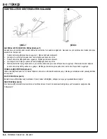
Page 32: ...STESİ Motor Çalışır Durumda 1 Ana ve yan süpürgelerde dönmeyi önleyecek çöp olmadığından emin olun NOT Süpürgelerden ve veya fırçalardan çöpleri temizlerken daima koruyucu eldiven takın 2 Lastik sileceklerde hasar olup olmadığını ve yere temas edip etmediklerini kontrol edin TEMİZLEYİCİYİ ÇALIŞTIRMAK İÇİN Park freninin bırakılmış olduğundan emin olun 1 Yan ve ana süpürgeleri zemine indirin Ana süp...

Page 33: ...en ana koridora B süpürün Bir zeminin veya bölümün tamamını bir seferde temizleyin 2 Süpürmeden önce büyük çöpleri toplayın 3 Makine hareket halindeyken direksiyonu keskin şekilde çevirmeyin Makine direksiyonun hareketine çok hassastır ani dönüşler yapmayın 4 Bir yolu mümkün olduğunca düz izleyin Direklere çarpmaktan ya da makinenin kenarlarını sürtmekten kaçının 5 Makineyi hareket ettirirken yön ...

Page 34: ...2 Huni döndürme ve boşaltma kolunu S ittirerek BOŞALTMA konumuna getirin Huni dönmeye başlayacaktır 3 Huninin dönme hızı iki katına çıktığında huni kaldırma kolu R çalışacaktır Huni kaldırma kolunu R KALDIRMA konumuna çekerek huniyi istenen seviyeye yükseltin MİNİMUM 8 inç ya da 20 cm KALDIRMA GEREKLİDİR 4 Boşaltma turunu tamamlamadan önce huni yukarı konumdayken 12 18 inç kadar yavaşça ileri sürü...

Page 35: ...eyen sıkıştırılmış havayla üflenerek temizlenebilir ya da sabunlu suyla yıkanabilir Tamamen kurumamış Filtre Panellerini kullanmaya çalışmayın TOZ KONTROL SİSTEMİ Çöp hunisindeki set sistemi makine süpürme yaparken havadaki tozu en aza indirecek şekilde tasarlanmıştır Süpürme çöpleri huniye atılır Pervane vakum fanı daha hafif tozu yukarı çeker ve set sisteminden geçirir Ön Temizleme Kapağı daha a...

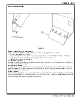
Page 36: ...apısını 10 A kapatın Motoru çalıştırın 11 Süpürge kolunu SÜPÜRME konumuna getirin 12 Süpürgeyi 30 saniye yerinde bırakın 13 Süpürge kolunu YUKARI konumuna getirin 14 Makineyi test noktasından geri çekin 15 Süpürge kıllarının yerle teması için süpürgenin süpürdüğü parlak yüzeyi kontrol edin Yerle süpürge kıllarının temas alanı 2 3 inç ya da 5 8 cm 16 genişliğinde olmalıdır ANA SÜPÜRGE SEVİYE AYARI ...

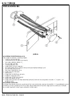
Page 37: ...u tertibatını süpürge indirildiğinde 3 derecelik bir açıyla zeminle temas etmesini sağlayacak bir konuma getirin YAN SÜPÜRGEYİ DEĞİŞTİRME Yan süpürge kaldırma kontrolünü YUKARI konumuna getirin Yan süpürgenin alt ortasındaki tespit vidasını sökün Yan süpürgeyi sökün Yan süpürge flanşını ara parçasını vidaları yıkayıcıları ve somunları değiştirilen yan süpürgeye aktarın Yeni yan süpürgeyi mile yerl...

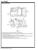
Page 38: ...ğlama prosedürlerini uygulayın Tahrik tekerleği rakor yatağını 2 B ve ön tekerlek yataklarını C iyi bir çok amaçlı yağ ile yağlayın Direksiyon kutusu tertibatının direksiyon kutusu muhafazasının ön kısmında bir gresörlüğü bulunmaktadır Bu gresörlükten direksiyon 3 kutusunu yağlamak için E P Lityum yağ kullanın Makinenin diğer bütün hareketli parçalarını 4 D 10 numara yağ ile yağlayın Gaz kablosunu...

Page 39: ...TÜRKÇE B 19 FORM NO 56041749 SR 2000 B 19 GENEL MAKİNE BAKIMI ...

Page 40: ...da aşınma veya kesik olup olmadığını kontrol edin 18 Ana fırçayı uçtan uca çevirin 19 Panel filtresini temizleyin veya değiştirin Önerilen motor bakımını gerçekleştirin Motor kılavuzuna bakın 100 SAATTE BİR 20 Karter yağını değiştirin 21 Motor yağı filtresini değiştirin 22 Tahrik tekerleği rakor yatağını yağlayın 23 Ön tekerlek yataklarını yağlayın 24 Direksiyon kutusunu yağlayın 25 Tüm hareketli ...

Page 41: ...l Model No 56516755 56516750 56516753 Ses Basıncı Seviyesi IEC 60335 2 72 2002 Değişikliği 1 2005 ISO 11201 dB A 92 3 Ses Gücü Seviyesi IEC 60335 2 72 2002 Değişikliği 1 2005 ISO 3744 dB A Lwa 112 1 Toplam Ağırlık lbs kg 3800 1724 El Kontrollerindeki Titreşimler ISO 5349 1 m s2 0 93 m s2 Koltuktaki Titreşimler EN 1032 m s2 0 54 m s2 Tırmanma 21 11 8 ...

Page 42: ......

Page 43: ...odepsaný stvrzuje že výše uvedený model byl vyroben v souladu s následujícími směrnicemi a normami SLO Spodaj podpisani potrjujem da je zgoraj omenjeni model izdelan v skladu z naslednjimi smernicami in standardi F Je soussigné certifie que les modèles ci dessus sont fabriqués conformément aux directives et normes suivantes NL Ondergetekende verzekert dat de bovengenoemde modellen geproduceerd zij...

Page 44: ...Nilfisk Advance A S Sognevej 25 DK 2605 Brøndby Denmark Tel 45 43 23 81 00 Fax 45 43 43 77 00 www nilfisk advance com ...

Reviews: