Nilfisk-Advance T40, Technical Manual
The Tannoy T40 User Manual is a comprehensive guide that provides detailed instructions on how to maximize the performance of your T40 speaker system. Easily accessible for free download from our website, this manual ensures you get the most out of your Tannoy T40 experience.
Share
Download


Reviews:
No comments
Related manuals for T40
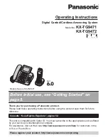
KX-TGK220E
Brand: Panasonic Pages: 16
KX-TG9472B
Brand: Panasonic Pages: 64
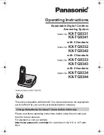
KX-TG9331T
Brand: Panasonic Pages: 60

F5
Brand: Jack Pages: 8

F5
Brand: Jack Pages: 10

BOS-18 II 56382453
Brand: Clarke Pages: 28

Royal 4000
Brand: EVA Pages: 56

PHANTOM H2
Brand: Cameo Pages: 52

RE1306
Brand: Janome Pages: 2

GBC StreamPunch Ultra
Brand: ACCO Brands Pages: 92

FOG1500MULTI
Brand: afx light Pages: 19

TFX-1032
Brand: Radio Shack Pages: 36

PAS20BA-BC
Brand: Powr-Flite Pages: 9

PLC-2760NVM
Brand: JUKI Pages: 42

Quantum Stylist Touch
Brand: Singer Pages: 4

1669U101
Brand: Singer Pages: 38

LK-1910
Brand: JUKI Pages: 187

LF8140.8145
Brand: Xerox Pages: 148


