background image

OPERATOR MANUAL 

4

146 0596 000(4)2004-02

MACHINE DESCRIPTION

TERRA 128B SWEEPER OPERATION 
CAPABILITIES

The TERRA 128B Sweeper is designed and construct-
ed to sweep non-hazardous dust or light debris on
smooth and solid floors, light carpeting,  in civil or indus-
trial environments, under safe operating conditions by

trained Operator

.

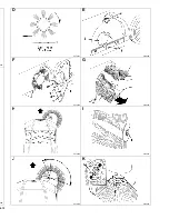
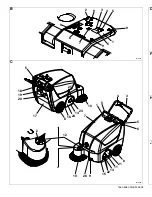
Control panel

(See Fig. B)
1.

Control panel

2.

Ignition key

3.

Discharged battery warning light

4.

Semi-discharged battery warning light

5.

Charged battery warning light

6.

Display

7.

Display selection button: hour counter/ hour and
minutes counter / battery voltage (V),

8.

Filter shaker push-button (optional)

9.

Panel fastening screws

Exterior general overview

(See Fig. C)
1.

Serial number plate / technical data 

2.

Side broom latch

3.

Handlebar

4.

Drive lever

5.

Knobs to adjust the handlebar inclination

6.

Can holder

7.

Hood

8.

Rear wheels

9.

Pivoting front wheel

10. Side broom
11. Main broom
12. Side broom lifting and adjusting knob
13. Left side skirt
14. Right side skirt
15. Front skirt
16. Rear skirt
17. Hopper
18. Hopper latch
19. Hopper handle
20. Manual filter-shaker handle
21. Main broom access door
22. Left main broom height adjuster 

Note: 

Forward, backward, front, rear, left or right
are intended with reference to the opera-
tor’s position, with the hands on the han-
dlebar (3, Fig. C).

23. Right adjuster of the main broom height
24. Main broom right door
25. Main broom right door fastening screws
26. Pedal brake on front wheel (optional)

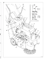
Under hood

(See Fig. T)
1.

Hood (open position)

2.

Batteries

3.

Battery connector

4.

Electronic battery charger

5.

Battery charger power cord

6.

Circuit breaker

7.

Side broom motor fuse

8.

Battery caps (Lead-acid battery)

9.

Lead (WET) or gel (GEL) battery selector switch
(positioned on the optional electronic battery
charger)

10. Battery connection diagram
11. Charged battery warning light
12. Main broom belt
13. Drive belt
14. Drive pulley for main broom
15. Drive pulley for rear wheels
16. Fan
17. Main electric motor
18. Signal circuit fuse
19. Hood opening switch
20. Serial number plate / technical data
21. Ground connection chain

TECHNICAL DATA

Dimensions

Values

Cleaning width 
(without side broom)

500 mm (19.69 in)

Cleaning width
(with side broom)

700 mm (27.6 in)

Machine length

1070 mm (42.13 in)

Machine width, 
(without side broom)

667 mm (26.26 in)

Height when the 
handlebar is lowered

836 mm (32.91 in)

Minimum height from ground

40 mm (1.6 in)

Handlebar height, (minimum/
maximum)

824/1120 mm
(32.4/44 in) 

Main broom size

ø 245 x 500 mm 
(9.65x19.69 in)

Side broom size

ø 347 mm (13.7 in)

Max speed

4.24 Km/h (2.63 mph)

Maximum slope

2 %

Hopper capacity

40  l (1.4 ft

3

Machine total weight 
(without battery)

94,78 Kg (210.62 lb)

Front wheel, steering

ø 125/37.5-50 mm
(4.92/1.48-1.97 in)

Summary of Contents for Terra 128B

Page 1: ...146 0596 000 4 2004 02 Terra 128B INSTRUCTIONS FOR USE Advance Model 908 4003 010 English French Spanish Portuguese ...

Page 2: ......

Page 3: ...146 0596 000 4 2004 02 B S310025 C S310069 D F H J 9 8 7 9 6 1 9 5 4 3 9 2 5 18 19 20 17 8 16 24 14 23 25 2 12 10 26 9 15 22 13 11 21 8 6 5 3 4 5 7 10 1 ...

Page 4: ...4 02 025 069 D S310027 E S310028 F S310029 G S310030 H S310068 I S310032 J S310070 K S310034 ...

Page 5: ...146 0596 000 4 2004 02 1 3 3 2 4 L S310035 M S310036 N S310037 O S310038 P S310039 Q S310040 R S310041 S S310042 T ...

Page 6: ... 02 0036 0038 0040 0042 T S310067 ...

Page 7: ...actionmainbroom 1460531000 EXT BRUSH MOTOR 146 0532 000 ELECTROMAGNETIC SWITCH 146 0626 000 KEY SWITCH 145 0372 000 HOODSAFETYSWITCH 1460565000 ELECTRONIC BOARD 146 0570 000 BATTERYCONNECTOR 1460747000 CHARGERCONNECTOR 1453735000 SW1 SW2 ES1 M2 F3 M1 F1 F2 CH1 EB1 CN1 CN2 Gel Pb verde GN YE WH PK RD VT OG GY bianco giallo rosso viola rosa arancio grigio COLORSCODES BK BU BN nero azzurro marrone GR...

Page 8: ...CHINE USE 5 BATTERY CHECK INSTALLATION ON A NEW MACHINE 5 BATTERY INSTALLATION AND BATTERY TYPE SETTING WET OR GEL 6 BEFORE START UP 6 STARTING AND STOPPING THE MACHINE 6 MACHINE OPERATION 7 EMPTYING THE HOPPER 7 AFTER MACHINE USE 7 PUSHING THE MACHINE 7 MACHINE STORAGE 7 MAINTENANCE 8 SCHEDULED MAINTENANCE TABLE 8 MAIN BROOM HEIGHT CHECK 9 MAIN BROOM REPLACEMENT 9 SIDE BROOM HEIGHT ADJUSTMENT 10 ...

Page 9: ...ied out by qualified personnel or by Advance Service Centers Only original spare parts and accessories should be used Call Advance for service or to order spare parts and ac cessories Specify the machine Model and Serial Num ber when discussing your machine MACHINE Model MACHINE Serial Number MODIFICATIONS AND IMPROVEMENTS Our Company constantly improves its products and re serves the right to mak...

Page 10: ...people DANGER WARNING Storage temperature must be within 32 F 104 F 0 C 40 C The machine working temperature must be within 32 F 104 F 0 C 40 C Humidity range should be within 30 and 95 Do not use the machine as a transport vehicle Do not allow the brooms to operate while the machine is stationary to avoid damaging the floor In case of fire use a powder extinguisher Do not use water Do not bump in...

Page 11: ...r s position with the hands on the han dlebar 3 Fig C 23 Right adjuster of the main broom height 24 Main broom right door 25 Main broom right door fastening screws 26 Pedal brake on front wheel optional Under hood See Fig T 1 Hood open position 2 Batteries 3 Battery connector 4 Electronic battery charger 5 Battery charger power cord 6 Circuit breaker 7 Side broom motor fuse 8 Battery caps Lead aci...

Page 12: ...cover these decals for any reason and in case of damage replace them immediately BATTERY CHECK INSTALLATION ON A NEW MACHINE The machine needs a 12 V battery or two 6 V batteries connected according to the diagram in Fig T 10 The machine can be equipped in one of the following ways a A lead or gel battery installed on the machine and ready to be used b A lead battery installed on the machine but w...

Page 13: ...ghly with water and consult a physician Battery has to be filled in a properly venti lated area Use protective gloves NOTE Battery charger must be connected to the batteries for machine to function 6 Install the jumper wire 1 Fig S on the WET connectors 2 Fig S for lead batteries or on the GEL connectors 3 Fig S for gel batteries 7 Reinstall the control panel and tighten the screws 9 Fig B 8 Recon...

Page 14: ...eriod and whenever it is full NOTE During this operation the electric motors and all machine functions are automati cally stopped NOTE When the hopper is full the machine can not collect more dust and debris CAUTION To avoid damaging the dust filter do not sweep wet floors or ground EMPTYING THE HOPPER 1 Release the drive lever to stop the machine 2 Turn the ignition key 2 Fig B to the 0 position ...

Page 15: ...y an autho rized service center This manual describes only the easiest and most com mon maintenance procedures NOTE For other maintenance procedures see the specific Service Manual that can be consulted at the Advance Service Center SCHEDULED MAINTENANCE TABLE For the related procedure see Service Manual 1 Or before each start Maintenance operation On delivery Every 10 hours Every 50 hours Every 1...

Page 16: ...mpromise the normal function of the machine and can overheat the elec trical components drastically reducing their life Pay particular attention when checking the main broom height broom pattern and never operate the machine outside the specifications listed above MAIN BROOM REPLACEMENT 1 With the machine on level ground activate the brake 26 Fig C if equipped or block the whe els 2 Turn the ignit...

Page 17: ...plicable to each type of brooms DUST FILTER CLEANING AND INTEGRITY CHECK 1 With the machine on level ground activate the brake pedal 26 Fig C if present or block the wheels 2 Turn the ignition key 2 Fig B to the 0 position 3 Disengage the hopper latch 18 Fig C 4 Using the handle 19 Fig C remove the hopper 17 Fig C from the machine 5 Rotate the filter clamp 1 Fig L upward approxi mately 90 and let ...

Page 18: ...10 mm see the Service Manual for Skirt Replacement 8 Check that the front and rear skirts 1 and 2 Fig Q rub lightly on the floor but are not completely lif ted by the ground see figure P 9 If necessary adjust the skirt height by loosening the four screws and using its slots 3 Fig Q 10 Install in the reverse order of removal BATTERY CHARGING 1 Drive the machine on level ground and activate the brak...

Page 19: ...rate Check the side broom fuse 7 Fig B integrity The machine operates only when stationary otherwise the red warning light turns on Re charge the battery If the problem persists replace the battery The circuit breaker 6 Fig T trips frequently Check if the main broom pattern is not wider than 4 cm 1 57 in Check that the machine is not working on slopes higher than 2 Check if debris is not blocking ...

Page 20: ...NSTALLATION DE LA BATTERIE ET ETABLISSEMENT DU TYPE DE BATTERIE WET OU GEL 18 AVANT LA MISE EN MARCHE 18 MISE EN MARCHE ET ARRET DE LA MACHINE 18 MACHINE AU TRAVAIL 19 DECHARGEMENT DU CONTENEUR DECHETS 19 APRES L UTILISATION DE LA MACHINE 19 MOUVEMENT DE LA MACHINE PAR POUSSEE 20 INACTIVITE PROLONGEE DE LA MACHINE 20 ENTRETIEN 20 PLAN D ENTRETIEN PROGRAMME 20 CONTROLE HAUTEUR BROSSE CENTRALE 21 RE...

Page 21: ...réparations si nécessaires il faut s adresser au personnel qualifié ou directement aux Centres de Service Après vente Advance et il ne faut utiliser que des pièces de rechange et accessoires ori Modèle MACHINE Numéro de série MACHINE ginaux Pour l assistance ou la commande de pièces de re change et accessoires contacter l organisation Advan ce en spécifiant toujours le Modèle et le Numéro de série...

Page 22: ...adient est supérieur à 2 DANGER ATTENTION Ne pas laver la machine avec des jets d eau directs ou sous pression ou avec des substances corro sives Ne pas utiliser air comprimé pour le nettoyage général de la machine Ne pas utiliser la machine dans des milieux particu lièrement poussiéreux Pendant l utilisation de cette machine faire attention à sauvegarder l intégrité des autres personnes La tempér...

Page 23: ...ère avant droite gauche ou arrière indi quées dans ce manuel doivent être considérées comme référées à l opérateur en position de conduite les mains sur le guidon 3 Fig C 2 Dispositif de retenue brosse latérale 3 Guidon 4 Levier d activation 5 Poignées pour le réglage d inclination du guidon 6 Porte objet 7 Coffre 8 Roues arrière sur axe fixe 9 Roue avant tournante 10 Brosse latérale 11 Brosse cen...

Page 24: ...T Fusible circuit de contrôle 18 Fig T ACCESSOIRES OPTIONS Outre les composants présents dans le modèle stan dard la machine peut être équipée avec les accessoi res optionnels suivants selon l emploi spécifique de la machine 1 Batterie s au gel 2 Brosses centrale et latérale avec poils plus ou moins durs par rapport au standard 3 Filtre poussières en polyester antistatique et en polyester BIA C 4 ...

Page 25: ...tion pendant l utilisation d aci de sulfurique à cause de sa corrosivité en cas de contact avec la peau ou les yeux laver et rincer abondamment à l eau et consulter un médecin Les batteries doivent être remplies dans un milieu bien aéré Utiliser les gants de protection de la carte électronique de la machine et du chargeur de batterie en opérant selon les indications suivantes Etablissement machine...

Page 26: ...porter la clé d activation en position 0 tirer la poignée 20 Fig C vers l extérieur jusqu à fin de course puis re lâcher Le ressort de rappel interne détermi nera un coup sur le cadre du filtre poussières en le secouant Répéter l opération décrite quelques fois Reporter la clé de mise en REMARQUE la brosse latérale 10 Fig C peut être baissée et soulevée même pendant son fonctionnement marche en po...

Page 27: ...es opérations d entretien programmé ou extra ordinaire doivent être effectuées par un personnel qua lifié ou par un Service Après vente autorisé Dans ce manuel seulement les procédés des opéra tions d entretien les plus simples et les plus récurrentes sont indiqués ci dessous ATTENTION opérations à exécuter avec la machine ar rêtée clé de mise en marche enlevée et quand requis avec la batterie déb...

Page 28: ...um est admise afin d obtenir la trace 1 Fig D de 2 à 4 cm 0 8 1 6 in définie au point 1 REMPLACEMENT BROSSE CENTRALE 1 Porter la machine sur une surface horizontale et si équipé activer le frein à pédale 26 Fig C 2 Tourner la clé de mise en marche 2 Fig B en position 0 3 Desserrer les pommeaux 1 Fig E sur les deux côtés de la machine 4 Déplacer les index 2 Fig E de variation hauteur brosse jusqu à...

Page 29: ...es sont équipées La procédure ici décrite est ap plicable à tous les types de brosse NETTOYAGE FILTRE POUSSIERES ET CONTROLE INTEGRITE 1 Porter la machine sur une surface horizontale et si équipé activer le frein à pédale 26 Fig C 2 Tourner la clé de mise en marche 2 Fig B en position 0 3 Décrocher le dispositif de retenue 18 Fig C 4 A l aide de la poignée 19 Fig C enlever le con teneur déchets 17...

Page 30: ... centrale comme décrit dans le paragraphe spécifique 6 Vérifier l intégrité du volet avant 1 Fig Q et du volet arrière 2 7 Remplacer les volets en présence de déchirures 1 Fig N supérieures à 20 mm ou de cassures 2 supérieures à 10 mm voir Manuel d entretien pour le remplacement des volets 8 Vérifier que les volets avant 1 Fig Q et arrière 2 frottent légèrement sur le plancher et que de toute faço...

Page 31: ...ger les batteries La brosse latérale ne fonctionne pas Vérifier l intégrité du fusible 7 Fig T La machine fonctionne exclusivement en état d arrêt mais sous effort la machine s éteint et le témoin lumineux rouge clignote Recharger la batterie Au cas où le problème persisterait remplacer la batterie Le coupe circuit 6 Fig T se déclenche fréquemment Vérifier que la trace laissée sur le sol par la br...

Page 32: ...ACION DEL TIPO DE BATERÍA WET O GEL 29 ANTES DE LA PUESTA EN MARCHA 29 PUESTA EN MARCHA Y PARADA DE LA MAQUINA 29 MAQUINA EN FUNCION 30 VACIADO DEL CAJON 30 DESPUES DE LA UTILIZACION DE LA MAQUINA 30 DESPLAZAMIENTO DE LA MAQUINA MEDIANTE EMPUJE 30 PERIODO DE LARGA INACTIVIDAD DE LA MAQUINA 31 MANTENIMIENTO 31 ESQUEMA DE MANTENIMIENTO PROGRAMADO 31 CONTROL ALTURA CEPILLO CENTRAL 32 SUSTITUCION DEL ...

Page 33: ...ZAS DE REPUESTO Y MANTENIMIENTO Para cualquier necesidad que se refiere a la utilización al mantenimiento suplementario y a las reparaciones consultar el personal calificado o los Centros de Asis Modelo MAQUINA Número de serie MAQUINA tencia Advance Se recomienda utilizar sólo piezas de repuesto y acesorios originales Para la asistencia o para ordenar piezas de repuesto o acesorios acuda a un Cent...

Page 34: ...a máquina en ambientes demasiado polvorientos Cuando se utiliza esta máquina tener cuidado de salvaguardar la incolumidad de las personas La temperatura de almacenamiento debe estar entre los 0 C y los 40 C La temperatura de la máquina en trabajo debe estar entre los 0 C y los 40 C La humedad debe estar entre el 30 y el 95 No utilizar la máquina como vehículo de transporte No permitir que los cepi...

Page 35: ...dor con las manos posicionadas sobre el manillar 3 Fig C 10 Cepillo lateral 11 Cepillo central 12 Empuñadura para levantar y ajustar la altura del cepillo lateral 13 Puerta abatible lateral izquierda 14 Puerta abatible lateral derecha 15 Puerta abatible delantera 16 Puerta abatible trasera 17 Cajón 18 Gancho del cajón 19 Manilla del cajón 20 Empuñadura del sacudidor del filtro manual 21 Portillo d...

Page 36: ...s componentes instalados en la versión estándar la máquina puede equiparse con los siguientes acesorios opciones según la utilización específica 1 Batería s de gel 2 Cepillos central y laterales con cerdas más o me nos duras con respeto al estándar 3 Filtro polvos de poliéster antistático y de poliéster BIA C 4 Sacudidor del filtro eléctrico 5 Rueda delantera con freno de pedal 6 Tipos diferentes ...

Page 37: ...a ATENCION Tener mucho cuidado cuando se usa áci do sulfúrico porque es muy corrosivo Si entra en contacto con la piel o los ojos la var a conciencia con agua y consultar un médico Rellenar la batería en áreas muy bien ven tiladas Utilizar guantes de protección baterías de plomo WET Si la regulación corres ponde al tipo de batería comprado pasar al párra fo siguiente en caso contrario llevar a cab...

Page 38: ... Repetir esta operación unas veces Portar la llave de encendido en posición I b Sacudidor del filtro eléctrico opcional te ner pulsado el pulsador del sacudidor del fil tro 8 Fig B durante unos segundos Repetir esta operación en media cada 10 mi nutos durante el trabajo cambiar el intervalo sobre la base de la cantidad de polvo presen te en el ambiente que se debe limpiar NOTA el cepillo lateral 1...

Page 39: ...n Centro de Asistencia autorizado En este manual se detallan sólo los procedimientos de mantenimiento más sencillos y frecuentes ATENCION efectuar estas operaciones con la máqui na apagada llave de encendido sacada y cuando pedido batería desconectada Además leer cuidadosamente todas las instrucciones del capítulo Seguridad NOTA para operaciones de mantenimiento su plementarias véase el Manual de ...

Page 40: ...ig D de 2 a 4 cm 0 8 1 6 in como indicado en el paso 1 SUSTITUCION DEL CEPILLO CENTRAL 1 Conducir la máquina sobre un suelo llano y acti var el freno de pedal 26 Fig C si instalado 2 Girar la llave de encendido 2 Fig B en posición 0 3 Aflojar las perillas 1 Fig E en ambos los lados de la máquina 4 Desplazar los indicadores 2 Fig E de variación de la altura del cepillo hasta que el cepillo alcan ce...

Page 41: ...cerdas más o menos du ras Este procedimiento es aplicable por cada uno de estos tipos LIMPIEZA FILTRO POLVOS Y CONTROL DE SU INTEGRIDAD 1 Conducir la máquina sobre un suelo llano y acti var el freno de pedal 26 Fig C si instalado 2 Girar la llave de encendido 2 Fig B en posición 0 3 Desenganchar el retén 18 Fig C 4 Mediante la manilla 19 Fig C quitar el cajón 17 Fig C 5 Girar la manilla 1 Fig L de...

Page 42: ...uertas abatibles delantera 1 Fig Q y trasera 2 7 Sustituir las puertas abatibles cuando hay cortes 1 Fig N más grandes de 10 mm o rupturas 2 más grandes de 10 mm para la sustitución de las puertas abatibles véase el Manual de Taller 8 Controlar que las puertas abatibles delantera 1 Fig Q y trasera 2 arrastren ligeramente contra el suelo y que de cualquier manera no sean des prendidas del suelo véa...

Page 43: ...nciona sólo cuando está parada en un punto si se intenta moverla se apaga y la luz de aviso roja parpadea Recargar la batería Si el problema sigue existiendo sustituir la batería El fusible de reactivación 6 Fig T salta frecuentemente Comprobar que la huella del cepillo central no sea superior a 4 cm 1 57 in Comprobar que la máquina no se haga funcionar sobre inclinaciones superiores al 2 Comproba...

Page 44: ...STALAÇÃO BATERIA E AJUSTE DO TIPO DE BATERIA WET OU GEL 42 ANTES DA PARTIDA 43 PARTIDA E PARADA DA MÁQUINA 43 MÁQUINA EM OPERAÇÃO 43 ESVAZIAMENTO DA GAVETA PORTA LIXO 43 APÓS O USO DA MÁQUINA 44 MOVIMENTO DA MÁQUINA POR IMPULSO 44 LONGA INACTIVIDADE DA MÁQUINA 44 MANUTENÇÃO 44 DIAGRAMA DE MANUTENÇÃO PROGRAMADA 45 VERIFICAÇÃO ALTURA DA ESCOVA CENTRAL 46 SUBSTITUIÇÃO DA ESCOVA CENTRAL 46 AJUSTE ALTU...

Page 45: ...al qualificado ou diretamente os centros de assistência Advance e de vem ser utilizadas peças de reposição e acessórios ori Modelo MÁQUINA Número de série MÁQUINA ginais Para assistência e para encomendar peças de reposi ção ou acessórios procurar pela organização Nil fisk Advance especificando sempre o Modelo e o Número de série MODIFICAÇÕES E MELHORIAS A nossa empresa procura por um constate ape...

Page 46: ...ente PERIGO ATENÇÃO Não utilizar em superfícies cujo gradiente superior a 2 Não lavar a máquina com jatos de água diretos ou sob pressão ou com substâncias corrosivas Devido à tipologia da máquina não usar ar comprimido em sua limpeza geral Não usar a máquina em ambientes particularmente poeirentos Durante o uso desta máquina prestar atenção em salvaguardar a incolumidade das demais pessoas A temp...

Page 47: ... dados técnicos 2 Retenção escova lateral 3 Guiador NOTA todas as referências a para frente para trás dianteiro direito esquerdo ou trase iro indicadas neste manual devem ser en tendidas como referidas ao operador com as mãos no guiador 3 Fig C 4 Alavanca de marcha 5 Manoplas para a regulação inclinação guiador 6 Porta objectos 7 Capota 8 Rodas traseiras em eixo fixo 9 Roda louca dianteira 10 Esco...

Page 48: ...83 15 7x10 3x11 1 in Aspiração e filtragem poeiras Filtro poeiras em papel de 5 10 µm 2 m2 22 ft2 Disp elétrico sacudimento filtro opcional 12V 30W Depressão do vão escova central 4 mm H2O 0 63 in H2O Diagramas Diagramas elétricos para as várias montagens opcionais Ver fig U PROTECÇÕES ELÉCTRICAS Fusível de armar 6 Fig T Fusível escova lateral 7 Fig T Sinal fusível 18 Fig T ACESSÓRIOS OPCIONAIS Al...

Page 49: ...atenção durante o emprego de ácido sulfúrico já que este é corrosivo em caso de contato com a pele ou os olhos lavar com grande quantidade de água e consultar um médico As baterias devem ser enchidas em uma área bem ventilada Utilizar luvas de protecção 5 Executar o carregamento da bateria ver procedi mento no Parágrafo Manutenção c Bateria não fornecida 1 Adquirir uma bateria adequada Ver parágra...

Page 50: ...r se que a gaveta do lixo 17 Fig C esteja correctamente fechada antes de partir a máquina NOTA a escova lateral 10 Fig C pode ser abaixada e erguida mesmo em funciona mento MÁQUINA EM OPERAÇÃO 1 Evitar de parar com a máquina por muito tempo na mesma posição com as escovas girando po dem se criar marcas indesejáveis no piso 2 Para um bom trabalho de varredura é necessário que o filtro poeiras estej...

Page 51: ...ias é oportuno executar as seguintes operações Desligar o conector 3 Fig T da bateria Erguer ligeiramente a máquina de modo que os flap a escova central e as rodas não toquem no chão Desligar o borne positivo da bateria diretamen te do pólo da bateria Guardar a máquina em uma adequada área de armazenagem coberta MANUTENÇÃO A operação adequada e segura da máquina é garanti da por meio de uma manute...

Page 52: ... visual das correias de transmissão tracção escova central Verificação altura e funcionamento dos flap Verificação altura das escovas lateral e central Limpeza filtro poeiras e verificação integridade 1 Verificação funcionamento dispositivo eléctrico sacudimento filtro opcional Controlo aperto porcas e parafusos Ajuste tensor correia tracção Substituição das correias de transmissão tracção escova ...

Page 53: ... D com largura de 2 a 4 cm definida no ponto 1 SUBSTITUIÇÃO DA ESCOVA CENTRAL 1 Posicionar a máquina em um terreno plano e se presente accionar o travão a pedal 26 Fig C 2 Levar a chave de partida 2 Fig B para a posição 0 3 Soltar as manoplas 1 fig E em ambos os lados da máquina 4 Deslocar os índices 2 Fig E de variação altura escova até levar a escova para a máxima distân cia do chão Aparafusar n...

Page 54: ...ure zas O presente procedimento é aplicável a todos os tipos de escova LIMPEZA FILTRO POEIRAS E VERIFICAÇÃO INTEGRIDADE 1 Posicionar a máquina em um terreno plano e se presente accionar o travão a pedal 26 Fig C 2 Levar a chave de partida 2 Fig B para a posição 0 3 Soltar a trava 18 Fig C 4 Extrair a gaveta porta lixo 17 por meio da maça neta 19 Fig C 5 Girar a maçaneta 1 Fig L de aproximadamente ...

Page 55: ...montagem orientar o filtro com a rede 2 Fig M voltada para a parte dianteira da máquina Verificação flap dianteiro e traseiro 5 Remover a Escova Central como previsto no Parágrafo específico 6 Verificar a integridade dos flap dianteiro 1 Fig Q e traseiro 2 7 Substituir os flap quando estiverem presentes cortes 1 Fig N de mais de 20 mm ou quebras 2 de mais de 10 mm ver o Service Manual para a Subst...

Page 56: ...Centros de As sistência Nilfisk os quais possuem o Manual de Oficina Service Manual PROBLEMA SOLUÇÃO Girando a chave para a posição I a máquina não parte Verificar a correcta conexão do conector 3 Fig T Verificar o correcto fechamento da capota Controlar o fusível de armar 6 Fig T Verificar integridade sinal fusível Verificar que o carregador de bateria esteja adequadamente ligado à bateria s e ou...

Page 57: ... autorizado Antes de sucatear a máquina é necessário em qual quer caso remover as seguintes partes 1 Bateria 2 Filtro poeiras em poliéster 3 Escovas central e lateral 4 Placa de circuitos ADVERTÊNCIA Os componentes removidos devem ser enviados a colectas diferenciadas em re speito da Normativa de higiene ambiental vigente ...

Page 58: ......

Page 59: ......
Page 60: ...Nilfisk Advance Inc 14600 21st Avenue North Plymouth MN 55447 3408 www nilfisk advance com Phone 800 989 2235 Fax 800 989 6566 2006 Nilfisk Advance Inc Plymouth MN 55447 3408 Printed in Italy ...

Reviews: