


OPERATOR MANUAL
146 0596 000(4)2004-02
5
Rear wheels, driving
ø 250 x 50 mm
(ø9.8x1.97 in)
Electric motor
600W (0.8 hp)
Weighted sound pressure
level (L
pA
)
64 dB(A)
Batteries
Standard battery
Lead, with acid
electrolyte
Optional battery
Gel, hermetic
Battery voltage
12 V
Usable battery capacity
Max. 240 Ah
Battery compartment size
398x262x283
(15.7x10.3x 11.1 in)
Dust control and filter
Paper dust filter 5-10 µm
2 m
2
(22 ft
2
)
Electric filter-shaker (optional)
12V, 30W
Vacuum in main broom
compartment
4 mm H
2
O
(0.63 in H
2
O)
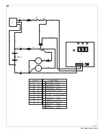
Diagram
Wiring diagram. See Figure U.
ELECTRICAL PROTECTIONS
Circuit breaker:
6, Fig. T
Side broom fuse:
7, Fig. T
Signal circuit fuse
18, Fig. T
ACCESSORIES / OPTIONS
In addiction to the standard components, the machine
can be equipped with the following accessories/op-
tions, according to the specific machine use:
1.
Gel battery/ies
2.
Main and side broom with harder and softer
bristles
3.
Antistatic polyester or polyester BIA C dust filter
4.
Electric filter shaker
5.
Front wheel with brake pedal
6.
Different skirt types
For further information concerning the optional acces-
sories, contact an authorized retailer.
MACHINE USE
Using this Manual, the operator must learn the meaning
of these symbols.
Do not cover these decals for any reason and in case
of damage, replace them immediately.
BATTERY CHECK/INSTALLATION ON A
NEW MACHINE
The machine needs a 12 V battery or two 6 V batteries
connected according to the diagram in Fig. T, 10.
The machine can be equipped in one of the following
ways:
a.
A lead or gel battery installed on the machine and
ready to be used.
b.
A lead battery installed on the machine but without
electrolyte.
c.
Without a battery.
According to these conditions, follow the instructions as
described below.
a.
Lead or gel battery installed on the machine
and ready to be used.
1.
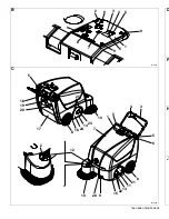
Open the hood (7, Fig. C) and check that the bat-
tery is connected to the machine using the appro-
priate connector (3, Fig. T).
2.
Lower the hood and check that it is closed correct-
ly (the hood must be as shown in Fig. C).
3.
Insert the ignition key (2, Fig. B) in the control pan-
el and turn it to the “I” position (without pulling the
lever 4, Fig. C).
If the green warning light (5, Fig. B) turns on, the
battery is charged and ready to be used.
Otherwise the battery needs to be charged (refers
to the procedure in the Maintenance chapter).
b.
Lead battery installed on the machine but
without liquid electrolyte
1.
Open the machine hood (7, Fig. C).
2.
Remove the battery caps (8, Fig. T).
WARNING!
On the machine there are some decals in-
dicating:
- DANGER
- WARNING
- CAUTION
- CONSULTATION
NOTE:
Battery charger must be connected to the
batteries for machine to function.
Summary of Contents for Terra 128B
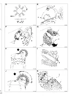
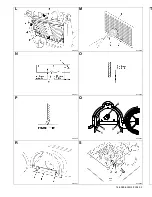
Page 2: ......
Page 4: ...4 02 025 069 D S310027 E S310028 F S310029 G S310030 H S310068 I S310032 J S310070 K S310034 ...
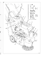
Page 6: ... 02 0036 0038 0040 0042 T S310067 ...
Page 58: ......
Page 59: ......


