INSTRUCTIONS FOR USE
146 1963 000(2)2006-06 –
Terra™ 3700B
7
Color code
BK:
Black
BU:
Blue
BN:
Brown
GN:
Green
GY:
Grey
OG:
Orange
PK:
Pink
RD:
Red
VT:
Violet
WH:
White
YE:
Yellow
Electrical fuses
The following fuses, which can be reset by pressing the
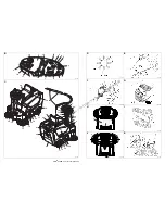
related key, are located under the hood (10, Fig. C):
– Drive fuse (11, Fig. U)
– Main broom/fan motor fuse (10, Fig. U)
–
Lamellar fuses, protected by a transparent plastic
cover (9, Fig. U), which protect the following circuits:
– F1 (25A): Main fuse (ignition switch circuit)
– F2 (25A): Filter shaker motor
– F3 (40A): Manual vacuum (optional)
– F4 (10A): Horn and pivoting light
– F5 (10A): Working light (optional)
– F6 (10A): Side broom motors
– F7 (25A): Spare fuse
– F8 (10A): Spare fuse
On the drive system electronic board there is the following
fuse:
– Drive system electronic board fuse (3 A)
ACCESSORIES/OPTIONS
In addition to the standard components, the machine can
be equipped with the following accessories/options,
according to the machine specific use:
–
Gel batteries;
–
Main and side brooms with harder or softer bristles;
–
Antistatic polyester or polyester BIA C dust filter;
–
Manual vacuum;
–
Working light;
–
Pivoting light;
–
Skirts of various material.
For further information concerning the optional
accessories, apply to an authorized retailer.
USE
While reading this manual, the operator must pay
particular attention to these symbols.
Do not cover these plates for any reason and immediately
replace them if they are damaged.
BATTERY CHECK/SETTING ON A NEW
MACHINE
The machine requires two 12V batteries or four 6V
batteries connected according to the diagram (20, Fig. U).
The machine can be set in one of the following modes:
a)
Lead or gel batteries installed on the machine and
ready to be used
1. Raise the machine hood (10, Fig. C) and engage
the hood support rod (3, Fig. U), then check that
the batteries are connected to the machine
through the special connector (6, Fig. U).
2. Disengage the hood support rod and lower the
hood. Check the hood is properly closed (the
machine must be as shown in Fig. C).
3. Insert the key into the ignition switch (2, Fig. B) on
the control panel and turn it to “I” position (without
pressing the pedal 5, Fig. C), then release it. If the
green warning light (5, Fig. B) turns on, the battery
is ready to be used. If the yellow (4, Fig. B) or red
(3, Fig. B) warning light turns on, it is necessary to
charge the batteries (see the relevant procedure
in the Maintenance chapter).
WARNING!
On some points of the machine there are
some adhesive plates indicating:
– DANGER
– WARNING
– CAUTION
– CONSULTATION
https://harrissupplyind.com - To Order Parts Call 608-268-8080


