background image

 Nilfisk ALTO

  Operator's Manual - 

SCRUBTEC R Manual Steering

SCRUBTEC R Manual Steering

SCRUBTEC R Manual Steering

SCRUBTEC R Manual Steering

SCRUBTEC R Manual Steering

                 Page  -15-

How To Install The Brush Or Pad on the BOOST
machine

To install the brush or pad on the BOOST machine, follow
this procedure:

1. Turn the key switch "ON".

2. Put the brush switch in the "UP" position.

3. Turn the key switch "OFF".

4. Go to the side of the machine.

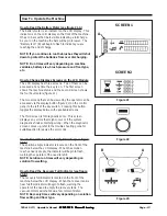
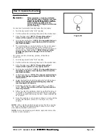
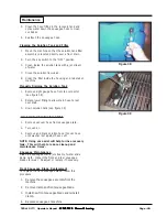
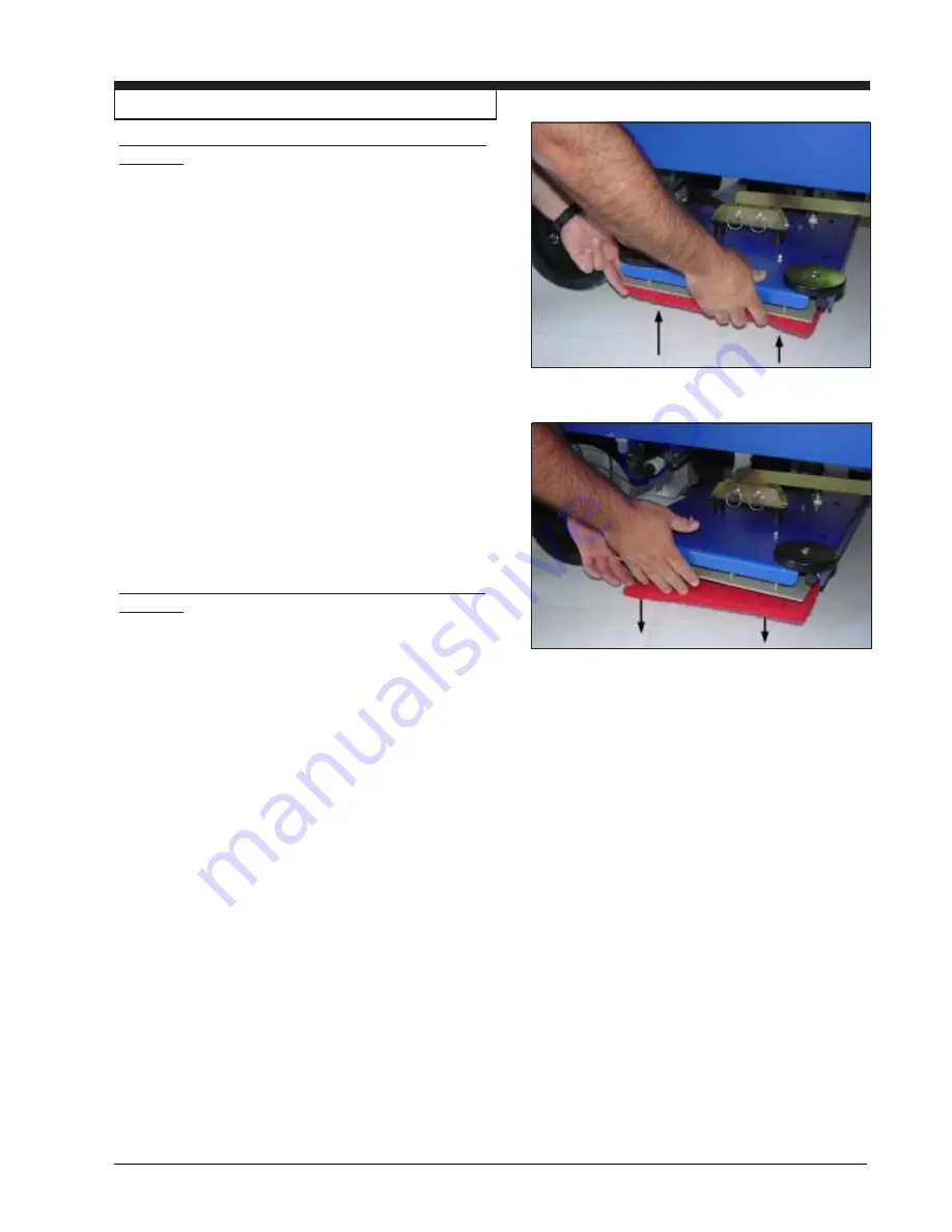
5. Press on a brush or pad under the flex plates.  See

figure 15.

NOTE: When using a black pad, position pad on
head. Lower head and operate momentarily to affix
pad to pad driver (if you have difficulty, position pad
on floor and lower head then operate.)

How To Remove The Brush Or Pad on the BOOST
machine

To remove the brush or pad from the machine, follow this
procedure:

1. Turn the key switch "ON".

2. Put the brush switch in the "UP" position.

3. Turn the key switch "OFF".

4. Go to the side of the machine.

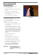
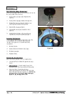
5. Pull downward on the brush or pad until it releases

from the flex plates.  See figure 16.

How To Prepare the Machine For Operation

Figure 15

Figure 16

Summary of Contents for SCRUBTEC BOOST R

Page 1: ...ding Manual Steering Models Manual Steering Models Manual Steering Models Manual Steering Models Manual Steering Models SCRUBTEC R 571 SCRUBTEC R 571 SCRUBTEC R 571 SCRUBTEC R 571 SCRUBTEC R 571 SCRUB...

Page 2: ...nt 25 Rear Squeegee Blade Replacement 26 SqueegeeMaintenance 26 Cleaning the Vac Hose 26 How to Correct Problems in the Machine 27 Common Error Codes 28 Accesories and Options 29 SECTION II Parts and...

Page 3: ...nes can cause an explosion when operated near flammable materials and vapors Do not use this machine with or near fuels grain dust solvents thinners or other flammable materials This machine is not su...

Page 4: ...w the regulations in your area Be aware of the environment hazards of chemicals that you dispose WARNING Only use the brushes provided with the appliance or those specified in the Operator s Manual Th...

Page 5: ...ake this item for environmentally safe recycling Business users should contact their supplier and check the terms and conditions of the purchase contract This product should not be mixed with other co...

Page 6: ...egee Up Down Solution Flow Switch Battery Meter LCDDisplay Button One Touch Button Forward Reverse Horn On Off Switch Recovery Solution LED WARNING READOPERATOR S MANUALBEFOREOPERATING THISMACHINE RIS...

Page 7: ...rent position of squeegee up or down Indicators are on showingcurrent settings Screens Available to Operator Battery blinks when low voltage occurs Water droplets off when solution is off and they are...

Page 8: ...ion the vacuum motor will turn on To raise the squeegee place the switch in either the middle or up position The middle position is used for one touch control The vacuum motor will stop after a short...

Page 9: ...be properly seated 2 The traverse speed can be adjusted by varying the pressure on the foot pedal NOTE During reverse motion the squeegee raises and the solution flow stops automatically Reverse also...

Page 10: ...nd is explosive Only charge batteries in a well ventilated area with the seat base lifted The batteries are fitted in the battery compartment under the seat and recovery tank figure 4 The machine uses...

Page 11: ...Electrolyte expands during charging As a result the electrolyte could overflow from the cells Always top off the cells with distilled water after charging CAUTION Irreversible damage will occur to th...

Page 12: ...tions To charge the batteries follow this procedure 1 Make sure the key switch is in the OFF position 2 Raise the seat base support 3 Connect the battery charger AC cord to a properly grounded wall re...

Page 13: ...e cuff to the squeegee hose fitting see figure 9 3 Tighten knobs NOTE Do not overtighten or break away feature is lost and damage may occur NOTE To prevent damage to the squeegee or machine the squeeg...

Page 14: ...the key switch OFF 2 Raise the brush skirt and pull out to remove See figure 11 3 Remove thumb screw from brush door See figure 12 4 Lower door approximately 12 mm and slide door and hub assembly from...

Page 15: ...Press on a brush or pad under the flex plates See figure15 NOTE When using a black pad position pad on head Lowerheadandoperatemomentarilytoaffix pad to paddriver ifyouhavedifficulty positionpad on fl...

Page 16: ...mit top speed If this happens stop and restart 5 After moving machine disengage manual brake override NOTE Machine will not function if override is engaged Seat Adjustment Standard The standard seat i...

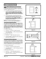
Page 17: ...ccessed via the display button figure 22 on the control panel to the left of the key switch Pressing this button toggles the display between the available screens The third screen is for diagnostics o...

Page 18: ...o accommodate many different floor conditions These different levels are shown on the LCD display on the front of the machine To adjust the amount ofsolutionapplied usetheSolutionFlowSwitch figure25 N...

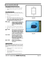
Page 19: ...ll the solution tank with clean water see figure 29 5 After filling the solution tank replace the solution tank lid WARNING Water solutions or cleaning materials used with this type of machine can lea...

Page 20: ...u stop the machine turn the key switch OFF and remove the key Do These Procedures When You Begin Your Work Period 1 Make sure the key switch is in the OFF position 2 Disconnect AC power from battery c...

Page 21: ...ing process follow these procedures 1 Turn the key switch to the OFF position 2 Put the water and a cleaning chemical in the solution tank 3 Sit on the driver seat NOTE The machine will not traverse i...

Page 22: ...solution flow off by decreasing the flow to its minimum position 2 Press the brush up down switch to the up position until the brush head has reached its up most position 3 Place the squeegee up down...

Page 23: ...Check the squeegee blade Use a cloth to clean the squeegee blade If the squeegee blade is damaged or worn turn or replace the blade NOTE To avoid damage to the squeegee the squeegee must be lifted wh...

Page 24: ...stallation Battery Inspection and Cleaning 1 Turn the key switch to the OFF position 2 To inspect batteries rotate seat support forward Lift and rotate recovery tank Be sure the recovery tank is empty...

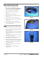
Page 25: ...sight gauge hose from top connector see figure 38 2 Rotate lower fitting to allow drain hose to rest over drain 3 Drain solution tank see figure 39 Vac Assisted Solution Tank Drain 1 Remove vacuum ho...

Page 26: ...ngs on the squeegee as required see How to Adjust Squeegee Squeegee Maintenance The squeegee blade may be rotated for longer life Keep sharp corner on floor for best cleaning results See figure 40 To...

Page 27: ...ecovery tank Put the squeegee in the low or middle position or reprogram one touch The operator must be properly seated in the driving position Turn the key to the ON position Remove the A C cord from...

Page 28: ...ime Brushes not fitted Drive system activated prior to turning key switch ON Make sure manual override is not engaged Poor or corroded connection to the battery Check the traction brush and vac motor...

Page 29: ...AND PAD DRIVERS SCRUBTEC R 571 Disc Model PARTNO DESCRIPTION 30556A Rear Squeegee Back Gum Rubber Blade 30067L Rear Squeegee Back Linatex Blade 30066A Rear Squeegee Front Ribbed Urethane Blade 30540A...

Page 30: ...Page 30 Nilfisk ALTO Operator s Manual SCRUBTEC R Manual Steering SCRUBTEC R Manual Steering SCRUBTEC R Manual Steering SCRUBTEC R Manual Steering SCRUBTEC R Manual Steering NOTES...

Page 31: ...No 6 557 207 No 7 185 397 and Patents Pending Manual Steering Models Manual Steering Models Manual Steering Models Manual Steering Models Manual Steering Models SCRUBTEC R 571 SCRUBTEC R 571 SCRUBTEC...

Page 32: ...Steering SCRUBTEC R Manual Steering SCRUBTEC R Manual Steering NilfiskALTO SCRUBTEC R 571 586 571 C BOOST SCRUBTEC R 571 586 571 C BOOST SCRUBTEC R 571 586 571 C BOOST SCRUBTEC R 571 586 571 C BOOST S...

Page 33: ...1 pg 62 Plate Electrical Cyl 1 pg 62 Plate Electrical Boost 1 4 pg 34 35 Mainframe Main Asm Rotary 1 pg 38 39 Mainframe Main Asm Boost 1 pg 36 37 Mainframe Main Asm Cyl 1 5 pg 42 Wheel Front Steering...

Page 34: ...nual Steering NilfiskALTO SCRUBTEC R 571 586 SCRUBTEC R 571 586 SCRUBTEC R 571 586 SCRUBTEC R 571 586 SCRUBTEC R 571 586 Main Frame Assembly Drawing Rotary 3 08 Drawing 11098A 35 41 38 41 42 42 41 40...

Page 35: ...Tension 1 14 61475A Clamp Transaxle 2 15 51609A Bumper Rear 2 16 962929 Screw 10 32 x 3 8 2 17 81221A Nut 1 2 20 Lug 8 18 61382A Wheel Anti Skid 2 19 40837A Transaxle 1 19A 40798A Brake 1 19B 41020A M...

Page 36: ...al Steering SCRUBTEC R Manual Steering NilfiskALTO SCRUBTEC R 571C SCRUBTEC R 571C SCRUBTEC R 571C SCRUBTEC R 571C SCRUBTEC R 571C Main Frame Assembly Drawing 3 08 Drawing 10949S 1 2 3 4 5 8 26 24 16...

Page 37: ...0883 Washer Lock 3 8 17 12 980645 Washer 3 8 SAE Flat 17 13 61473A Linkage Rod 4 14 53493A Pin Quick Release Actuator Btm 1 15 61718A Carriage Weldment 1 16 962244 Bolt 3 8 16 x 75 Hex 10 17 61475A Cl...

Page 38: ...Steering SCRUBTEC R Manual Steering SCRUBTEC R Manual Steering 1 2 3 4 5 2A 2B 6 7 8 5 6 7 9 10 11 12 12A 12B 13 6 7 14 15 16 17 18 19 20 21 22 23 24 25 26 27 28 29 NilfiskALTO SCRUBTEC BOOST SCRUBTE...

Page 39: ...1 12A 40798A Brake 1 12B 41020A Motor 1 13 962244 Bolt 3 8 16 x 75 Hex 7 14 85813A Screw 5 16 18 x 1 Hex Hd 2 15 980652 Washer 5 16 Lock 2 16 61836A Bracket Squeegee Stop 1 17 61719A Frame Main Weldme...

Page 40: ...ing SCRUBTEC R Manual Steering SCRUBTEC R Manual Steering SCRUBTEC R Manual Steering NilfiskALTO SCRUBTEC R 571 586 SCRUBTEC R 571 586 SCRUBTEC R 571 586 SCRUBTEC R 571 586 SCRUBTEC R 571 586 Optional...

Page 41: ...Description Qty 1 87624A Washer Nylon 1 1 2 x 1 4 x 1 8 2 2 86004A Screw 1 4 20 x 1 50 HHCS 1 3 920296 Nut 10 24 Elastic Stop 1 4 61699A Bracket Sq Lift Cable 1 5 962798 Screw 10 24 x 1 2 PH 1 6 8367...

Page 42: ...t 6 07 Drawing 10779A Ref Part No Description Qty 1 80267A Bolt 3 4 16 Hex Head 1 2 61472A Yoke Weldment Steering 1 3 980645 Washer 3 8 Flat 4 4 170883 Washer Lock 3 8 4 5 85822A Screw 3 8 16 x 7 8 He...

Page 43: ...er 1 4 Flat SS 6 10 61552A Lever Spring 1 11 920110 Nut 5 16 18 Hex Lock 1 12 920296 Nut 10 24 Elastic Stop 1 13 81104A Nut 1 4 Nylock 5 14 170915 Screw 1 4 20 x 3 4 Hex HD 2 15 962620 Screw 5 16 24 x...

Page 44: ...ing NilfiskALTO SCRUBTEC R 571 586 571 C BOOST SCRUBTEC R 571 586 571 C BOOST SCRUBTEC R 571 586 571 C BOOST SCRUBTEC R 571 586 571 C BOOST SCRUBTEC R 571 586 571 C BOOST R R R R R Recovery Tank Assem...

Page 45: ...el 1 14 920797 Nut Drain Valve 1 15 30623A Tube Stand Straight 1 16 643418 Gasket Vac Unit 1 17 58533A Spacer Vac Motor 3 18 45019A Motor Vac 1 18A 40830A Carbon Brush 2 19 41809A Contact Housing Conn...

Page 46: ...SCRUBTEC R Manual Steering NilfiskALTO SCRUBTEC R 571 586 571 C BOOST SCRUBTEC R 571 586 571 C BOOST SCRUBTEC R 571 586 571 C BOOST SCRUBTEC R 571 586 571 C BOOST SCRUBTEC R 571 586 571 C BOOST R R R...

Page 47: ...at Assembly 1 5 85395A Screw 1 4 20 x 1 2 PH 9 6 81112A Nut 5 16 18 Thin ESNA 1 7 61490A Mount Seat Assembly 1 8 61489A Plate Cover 1 9 70883A Label Battery Charger 1 10 980652 Washer 5 16 Lock 8 11 3...

Page 48: ...Manual Steering SCRUBTEC R Manual Steering NilfiskALTO SCRUBTEC R 571 586 571 C BOOST SCRUBTEC R 571 586 571 C BOOST SCRUBTEC R 571 586 571 C BOOST SCRUBTEC R 571 586 571 C BOOST SCRUBTEC R 571 586 57...

Page 49: ...o Description Qty 1 30530A Tank Solution 1 2 962957 Screw 10 16 x 1 2 Self Tap 8 3 87036A Washer 10 Flat 2 4 30539B Lid Solution 1 5 30578A Gasket Solution Tank Fill 1 6 61574A Bracket Tank Fill Gaske...

Page 50: ...ALTO SCRUBTEC R 571 586 571 C BOOST SCRUBTEC R 571 586 571 C BOOST SCRUBTEC R 571 586 571 C BOOST SCRUBTEC R 571 586 571 C BOOST SCRUBTEC R 571 586 571 C BOOST R R R R R Steering Column Assembly Drawi...

Page 51: ...1 4 20 x 1 2 HHCS 8 28 980657 Washer Lock 1 4 8 29 61837A Plate Column Adapter 1 30 980645 Washer 3 8 SAE Flat 4 31 80088A Screw M10 1 5 x 30MM 4 32 30734A Cover Front Lower 1 33 56003268 Retainer 1...

Page 52: ...Screw 5 16 18 x 1 1 2 FH 1 10 53838A Wheel Guide 4 1 11 920108 Nut 8 32 ESNA SS 4 12 55721A Latch Brush Housing 2 13 30535A Housing 28 Brush Right Main 1 14 962030 Screw 8 32 x 3 8 FHCS 4 Ref Part No...

Page 53: ...Screw 5 16 18 x 1 1 2 FH 1 10 53838A Wheel Guide 4 1 11 920108 Nut 8 32 4 12 55721A Latch Brush Housing 2 13 30537A Housing 34 Brush Right Main 1 14 962030 Screw 8 32 x 3 8 FHCS 4 Ref Part No Descrip...

Page 54: ...Manual Steering NilfiskALTO SCRUBTEC R 571 C SCRUBTEC R 571 C SCRUBTEC R 571 C SCRUBTEC R 571 C SCRUBTEC R 571 C 571 Cylindrical Head Assembly Drawing 5 05 Drawing 10962A 1 2 3 4 5 6 7 8 9 10 11 12 13...

Page 55: ...s 1 17 61743A Cover Cyl Head Belt 2 18 84237A Screw 10 32 x 50 P H 6 19 61752A Plate Skirt L H 1 20 80240A Screw 10 32 x 3 8 F H 14 21 30312A Skirt Side 2 22 61336A Spacer Binding 4 23 962094 Screw 10...

Page 56: ...Steering SCRUBTEC R Manual Steering SCRUBTEC R Manual Steering NilfiskALTO SCRUBTEC BOOST SCRUBTEC BOOST SCRUBTEC BOOST SCRUBTEC BOOST SCRUBTEC BOOST R R R R R BOOST Head Assembly Drawing 10 06 Drawin...

Page 57: ...4 10 962098 Screw 20 x 3 4 FH 4 11 61753A Eccentric 1 12 61775A Retainer Bearing 1 13 50736A Bearing 1 14 85737A Screw 20 x HHCS 1 15 11172A Isolator Deck 1 16 980614 Washer Starlock Ext 8 17 30664A...

Page 58: ...anual Steering SCRUBTEC R Manual Steering NilfiskALTO SCRUBTEC R 571 586 571 C BOOST SCRUBTEC R 571 586 571 C BOOST SCRUBTEC R 571 586 571 C BOOST SCRUBTEC R 571 586 571 C BOOST SCRUBTEC R 571 586 571...

Page 59: ...0 50835A Latch SqueegeeClamp 1 1 1 11 930086 Rivet 3 16 x 450 Aluminum 2 2 2 12 60252A Strap Clamp SqueegeeRetainer39 1 60232A Strap Clamp Squeegee Retainer 32 1 61885A Strap Clamp SqueegeeRetainer41...

Page 60: ...Drawing 10694A Ref Part No Description Qty 1 80275A Screw 1 4 14 x 3 4 3 2 53185A Ring Retainer 1 3 30048A Wheel Guide 1 4 61496A Weldment Fr Squeegee Base 1 5 81104A Nut 1 4 Nylock 1 6 59932A Wheel S...

Page 61: ...UBTEC R 571 586 SCRUBTEC R 571 586 Front Squeegee Arm Assembly Drawing and Parts List 5 05 Rotary Machine Only Drawing 10694A Ref Part No Description Qty 1 61548A Arm Weldment Squeegee 1 2 81112A Nut...

Page 62: ...83302A Stud 1 4 20 1 5 87026A Washer 1 4 Flat SS 8 6 980657 Washer Lock 1 4 7 7 81104A Nut 1 4 Nylock 1 8 41801A Contactor Main 36V 1 9 962430 Screw 1 4 20 x 1 2 HHCS 2 10 962113 Screw 10 32 x 1 00 P...

Page 63: ...ual Steering SCRUBTEC R Manual Steering SCRUBTEC R Manual Steering Page 63 NilfiskALTO SCRUBTEC R 571 586 571 C BOOST SCRUBTEC R 571 586 571 C BOOST SCRUBTEC R 571 586 571 C BOOST SCRUBTEC R 571 586 5...

Page 64: ...EC R Manual Steering SCRUBTEC R Manual Steering SCRUBTEC R Manual Steering NilfiskALTO SCRUBTEC R 571 586 571 C BOOST SCRUBTEC R 571 586 571 C BOOST SCRUBTEC R 571 586 571 C BOOST SCRUBTEC R 571 586 5...

Page 65: ...ual Steering SCRUBTEC R Manual Steering SCRUBTEC R Manual Steering Page 65 NilfiskALTO SCRUBTEC R 571 586 571 C BOOST SCRUBTEC R 571 586 571 C BOOST SCRUBTEC R 571 586 571 C BOOST SCRUBTEC R 571 586 5...

Page 66: ...EC R Manual Steering SCRUBTEC R Manual Steering SCRUBTEC R Manual Steering NilfiskALTO SCRUBTEC R 571 586 571 C BOOST SCRUBTEC R 571 586 571 C BOOST SCRUBTEC R 571 586 571 C BOOST SCRUBTEC R 571 586 5...

Page 67: ...UBTEC R Manual Steering SCRUBTEC R Manual Steering SCRUBTEC R Manual Steering Page 67 NilfiskALTO SCRUBTEC R 571 586 571 C BOOST SCRUBTEC R 571 586 571 C BOOST SCRUBTEC R 571 586 571 C BOOST SCRUBTEC...

Page 68: ...R Manual Steering SCRUBTEC R Manual Steering SCRUBTEC R Manual Steering NilfiskALTO SCRUBTEC R 571 586 571 C BOOST SCRUBTEC R 571 586 571 C BOOST SCRUBTEC R 571 586 571 C BOOST SCRUBTEC R 571 586 571...

Page 69: ...Nilfisk ALTO Operator s Manual SCRUBTEC R Manual Steering SCRUBTEC R Manual Steering SCRUBTEC R Manual Steering SCRUBTEC R Manual Steering SCRUBTEC R Manual Steering Page 69 NOTES...

Page 70: ...RK Nilfisk ALTO Division of Nilfisk Advance A S Industrivej 1 9560 Hadsund Denmark Tel 45 72 18 21 00 Fax 45 72 18 21 11 E mail salg nilfisk alto dk E mail service nilfisk alto dk www nilfisk alto dk...

Reviews: