background image

ELCART

ELCART DISTRIBUTION SPA  via Michelangelo Buonarroti, 46 - 20093 Cologno Monzese (Milano) ITALY

Tel. +39 02.25117310 Fax +39 02.25117610 sito internet:  www.elcart.com    e-mail: info@elcart.it

Manuale di istruzioni/Scheda tecnica

La divulgazione dei dati contenuti in questa scheda è da ritenersi un servizio puramente informativo e non costituisce alcun vincolo da parte della Elcart in merito a prestazioni ed utilizzo del prodotto.

The divulgation of data contained on this technical sheet are exclusively for informational reasons and establish no link on behalf of Elcart regard to thr performances and the usa of the product.
La divulgacion de los datos contenidos en esta ficha son un servicio unicamente informativo y no constituyen ningun vinculo de parte de Elcart respecto a las prestaciones y uso del producto.

ART. 09/09600-00

PAGINA 7 DI 12

1. SAFETY INFORMATION 

1.1 Preliminary 

'RVDQGGRQ·WV

1.3 Symbols 
1.4 Precautions 

2. DESCRIPTION 

2.1 Names of parts
2.2 Switches, buttons and 

LQSXWMDFNV

2.3 Display 

3. SPECIFICATIONS 

3.1 General 
3.2 Technical index 

4. OPERATING 
INSTRUCTIONS


4.1 Function switching 
4.2 Range switching 
4.3 Maximum value 
measurement 
4.4 Reading holding 
4.5 Backlight source 
4.6 Use of the test key 
4.7 Preparation for 
measurement 
4.8 Measurement of DC 
voltage
4.9 Measurement of AC 
voltage 
4.10 Diode test 
4.11 Circuit continuity test 
4.12 Resistance measurement 

1.1.5 Using the test probes supplied can ensure safety. 
If required, they must be replaced with those of the same 
model or class.

'RVDQGGRQ·WV

8VHWKHULJKWLQSXWMDFNIXQFWLRQDQGUDQJH

1.2.2 Do not take measurements beyond the protection 

OLPLWVLQGLFDWHGLQWKHVSHFLÀFDWLRQV

1.2.3 Do not touch the metal tips of the test probes when 
connecting the meter to the circuit to be measured.

 .HHS \RXU ÀQJHUV EHKLQG WKH SUREH EDUULHUV ZKHQ

taking a measurement with an effective voltage of above 
60V DC or 30V AC.
1.2.5 Do not take any voltage measurement if the value 
between the measuring terminal and the ground exceeds 
1000V.
1.2.6 Select the highest range if the value to be measured in 
the manual range is unknown.
1.2.7 Do not connect the meter to any voltage source while 
the meter is in the current, resistance, diode or continuity 
test range.
1.2.8 Disconnect the test probes from the circuit under test 
before turning the range selector to change functions.
1.2.9 Be careful that high voltage pulses at the test point 
may damage the meter when measurements are being 
taken on the switching power   circuit of a TV set.
1.2.10 Do not measure the resistance, diode or continuity 
of live circuits.
1.2.11 Do not use the meter near explosive gases, steam 
or dirt.
1.2.12 Stop using the meter if any abnormalities or faults 
are noticed.
1.2.13 Do not use the meter unless its rear case is securely 


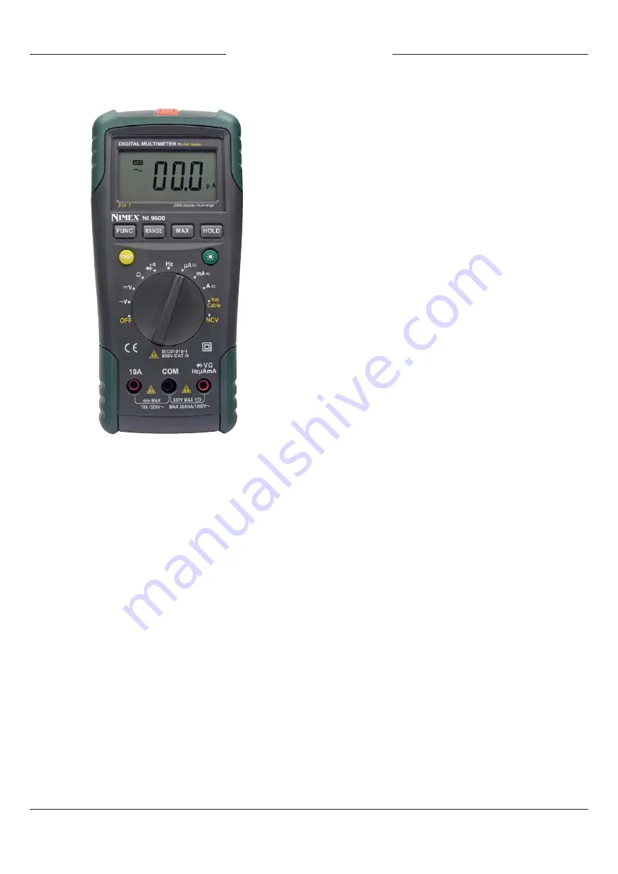
MULTIFUNCTION DIGITAL ART. 09/09600-00 MULTIMETER NIMEX NI-9600

INSTRUCTION MANUAL

1. SAFETY INFORMATION
Warning
BE EXTREMELY CAREFUL WHEN USING THE METER. 

,PSURSHUXVHRIWKLVGHYLFHFDQUHVXOWLQHOHFWULFVKRFN
RU GHVWUXFWLRQ RI WKH PHWHU 7DNH DOO QRUPDO VDIHW\

precautions and follow the safeguards suggested in 

WKLV PDQXDO 7R H[SORLW IXOO IXQFWLRQDOLW\ RI WKH PHWHU
DQGHQVXUHVDIHRSHUDWLRQ3URWHFWLRQSURYLGHGE\WKH

instrument will be impaired if used in a manner not 

VSHFLÀHGE\WKHPDQXIDFWXUHU

The Auto Range Digital Multimeter (hereinafter referred to 
as “the meter”) complies with the safety requirements for 
electronic measuring instruments in IEC-61010-1, falls into 
pollution degree 2 and meets the over-voltage standard of 
CAT III 600V.
Follow all safety and operation instructions to ensure safe 
use of the meter.
With proper use and care, the meter will give you years of 
satisfactory service.

3UHOLPLQDU\

1.1.1 To operate the meter, the user must observe the 
following normal safety rules:
1) General protection against electric shock; and
2) Protection of the meter against misuse
1.1.2 When the meter is received, please check whether it 
has been damaged during transport.
1.1.3 After being stored and delivered under harsh 

FRQGLWLRQVWKHPHWHUVKRXOGEHFKHFNHGDQGFRQÀUPHGIRU

damage.
1.1.4 The test probes must be kept in good condition. Check 
whether the insulation of the test probes has been damaged 
and whether any wire has been exposed.

4.13 Measurement of DC 
current 
4.14 Measurement of AC 
current 
4.15 Frequency Measurement 
4.16 Network cable integrity 
test 
4.17 Non-contact voltage 
detection 
4.18 Operating precautions of 
protective cover
4.20 Automatic power off

5. MAINTENANCE 

5.1 Replacement of batteries 
5.2 Replacement of fuse 
5.3 Replacement of test 
probes

6. ACCESSORIES 

Summary of Contents for NI 96000

Page 1: ...ventuali tensioni di picco che potrebbero generarsi sul circuito e che potrebbero danneggiare lo strumento 1 2 10 Non misurate resistenza diodi o continuità su circuiti alimentati 1 2 11 Non utilizzate lo strumento vicino a gas esplosivi vapori o sporcizia 1 2 12 In caso di misurazioni anormali fate controllare il PXOWLPHWUR GD SHUVRQDOH TXDOLÀFDWR 1 2 13 Non utilizzate lo strumento senza il coper...

Page 2: ...ttery indication are provided It is an ideal multifunctional instrument with scores of practical applications for professional factory school amateur and home use Il multimetro ha entrambe le funzioni auto manual range Il multimetro ha la funzione di autospegnimento Il multimetro ha la funzione data hold Il multimetro ha la funzione misurazione massimo O PXOWLPHWUR KD O LQGLFDWRUH GL EDWWHULD VFDU...

Page 3: ...ione Funzione Suonerà il buzzer se la resistenza è LQIHULRUH DL Range Risoluzione Precisione 200mV 0 1mV 0 8 della lettura 5 digits 2V 1mV 20V 0 01V 200V 0 1V 1000V 1V Max tensione di ingresso 1000V DC NOTA Nelle gamme di misurazioni di bassa tensione il risultato SRWUHEEH QRQ HVVHUH VWDELOH SHU O HOHYDWD VHQVLELOLWj GHOOR strumento 3 2 2 Tensione CA Max tensione di ingresso 750V AC Risposta in Fr...

Page 4: ... risultato NOTE 1 Durante misurazioni a bassa tensione potrebbero essere visualizzati dei valori anche se i terminali non sono collegati DO FLUFXLWR 4XHVWR q GRYXWR DOO HOHYDWD VHQVLELOLWj GHOOR strumento Quando i puntali verranno collegati al circuito il valore verrà visualizzato correttamente 2 Nella funzionalità manuale se il display visualizzerà OL R 2 µ VLJQLÀFD FKH OD JDPPD GL PLVXUD LRQH VH...

Page 5: ...CA 4 14 1 Inserite il puntale nero nel terminale COM Se la corrente da misurare è inferiore a 200mA inserite il puntale URVVR QHO WHUPLQDOH X P MDFN VH OD FRUUHQWH GD PLVXUDUH è compresa tra 200mA e 10A inserite il puntale rosso nel terminale 10A 4 14 2 Selezionate con la manopola la gamma di misura di corrente desiderata 4 14 3 Premete il tasto FUNC per selezionare la modalità CA e il tasto RANGE...

Page 6: ...erie nuove e richiudete il coperchio 5 2 Sostituzione Fusibile ATTENZIONE Prima di aprire il coperchio delle batterie rimuovete i puntali dal circuito da misurare per evitare il rischio di scosse elettriche Per evitare guasti e malfunzionamenti assicuratevi di utilizzare il giusto fusibile 5 2 1 Spegnete lo strumento e rimuovete i puntali dai terminali 5 2 2 Rimuovete il coperchio posteriore con u...

Page 7: ...current resistance diode or continuity test range 1 2 8 Disconnect the test probes from the circuit under test before turning the range selector to change functions 1 2 9 Be careful that high voltage pulses at the test point may damage the meter when measurements are being taken on the switching power circuit of a TV set 1 2 10 Do not measure the resistance diode or continuity of live circuits 1 2...

Page 8: ...r if it will idle for a long time 1 4 8 Using this appliance in an environment with a VWURQJ UDGLDWHG UDGLR IUHTXHQF HOHFWURPDJQHWLF ÀHOG DSSUR LPDWHO 9 P PD LQÁXHQFH LWV PHDVXULQJ accuracy The measuring result can be strongly deviating from the actual value 2 DESCRIPTION The meter is a portable specialized measuring instrument with a large digital LCD as well as a backlight source for easy readin...

Page 9: ...uick acting 3 1 14Battery under voltage indication The LCD displays the symbol 3 1 15Operating power 6F22 9V batteries 3 1 16 Operating temperature 0 C 40 C 3 1 17 Storage temperature 10 C 50 C 3 1 18Dimensions 195 92 55mm 3 1 19Weight about 400g including batteries 3 2 Technical index 3 2 1 DC Voltage Max input voltage 1000V DC NOTE At the low voltage range unsteady readings will appear before th...

Page 10: ...LV ORZ DERXW 9 WKH ZLOO GLVSOD WKH symbol when the batteries must be replaced 2 The symbol beside the input line indicates that the input voltage or current should not exceed the indicated value This is intended to protect the internal circuit from damage 3 Set the range selector to the desired measurement function and range In the manual range mode if the scale of the measured value is unknown be...

Page 11: ...tor to the desired current range position 4 13 3 Press the FUNC key to switch to DC measurement mode and press the RANGE key to select the auto or manual mode 4 13 4 Connect the test probes to the circuit under test in series for measurement 4 13 5 Take a reading in the main display area of the LCD The polarity indication will show the polarity of the terminal connected by the red probe NOTE Q WKH...

Page 12: ...r will be shut down and enter the sleeping mode to save electricity 4 19 2 To disable the automatic power off function hold on to the HOLD key to start up the meter or press the HOLD key in the sleeping mode to wake it up 5 MAINTENANCE 5 1 Replacement of batteries 5 1 1 When the symbol is displayed the batteries should be replaced immediately 5 1 2 Turn the range selector to OFF and remove the tes...

Reviews: