4. Installation
4. Installation
.10.
.11.
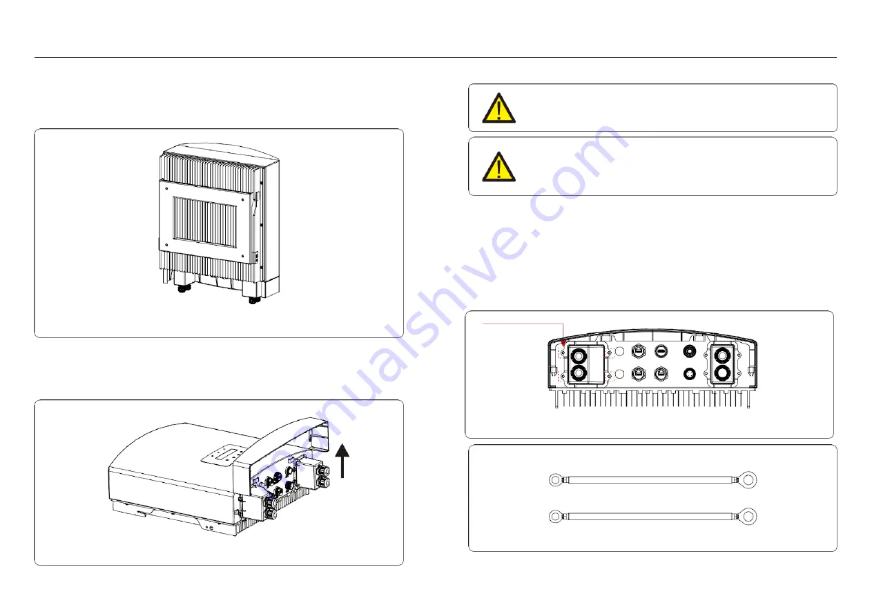
Figure 4.6 Remove the cover
BAT(+)
B)
BAT(-)
Battery(-)
Figure 4.8
2.Lift up the inverter ( be careful to avoid body strain), and align the back bracket on the
inverter with the convex section of the mounting bracket. Hang the inverter on the
mounting bracket and make sure the inverter is secured (see Figure 4.5)
4.3 Assemble the Battery Cables
Step 1. Please unlock the 4*M4 screws on the battery port protection cover as shown in the below
figure.
Step 2. Insert the battery power cables (in package) into the water-proof swivel nut on the cover,
(Break the plastic film on it).
Step 3. Fasten the battery power cables onto the BAT+ and BAT- terminals on the inverter. Please
make sure the labels on cable and inverter match up.
Step 4. Lock the 4*M4 screws and fix the cover onto the inverter.
Step 5. Connect the other side of the battery power cables to the battery.
Please make sure to remove the cover at the bottom of the inverter before assembling the
terminals.
Remove the cover as shown in the picture and follow the direction to lift the cover, make sure
the buckles on the left and right sides are correctly loosened.
WARNING:
To avoid DC Arc, Solis recommends installing DC switch between batteries and
AC-Coupled Inverter.
Ensure the correct polarity of batteries before connecting to the inverter.
WARNING:
Incorrect polarity of the battery cable may lead to permanent damage on
the device.
Figure 4.5 Wall mount bracket
M4 cross screws
DO
CT/Meter
WIFI
CAN
DRM
COM
Figure 4.7


