NIP
Pollux GigE Series – 01M / 05M Camera
Page
43
of
56 Manual 1.0
4.10.2
Line1 Opto-isolated Output Circuit
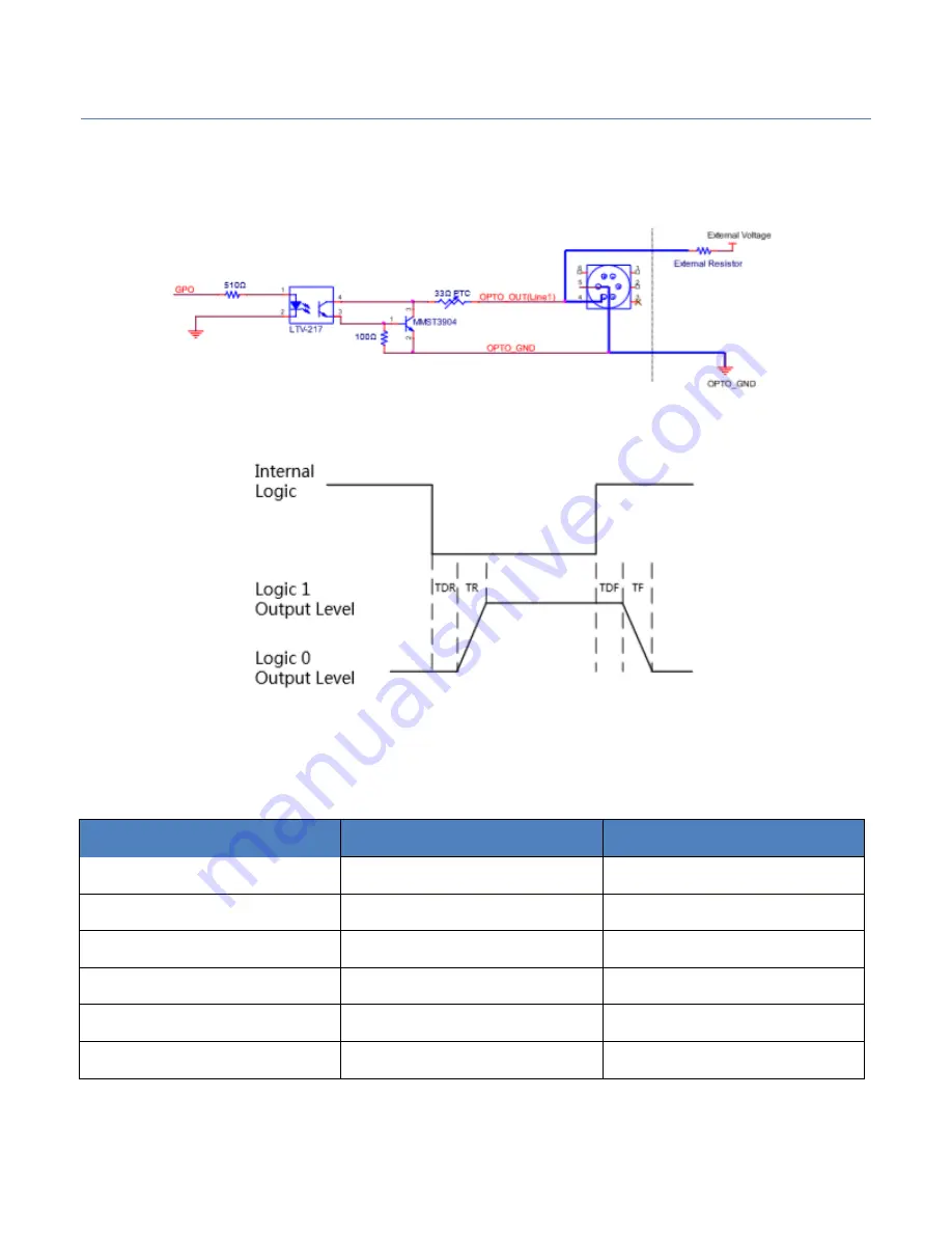
In controlling I/O, Line1 output circuit can be shown in Figure 56.
Figure 56.
Input Logic Level
Maximum Line1 output current: 25 mA
Figure 57.
Output Logic Level
Opto-isolated output electric feature can be shown in Table 3-5 (The external
voltage is 3.3 V and the external resistance is 1 K.)
Parameter
Symbol
Value
Output Logic Low Level
VL
575mV
Output Logic High Level
VH
3.3V
Output Rising Time
TR
8.4 us
Output Falling Time
TF
1.9us
Output Rising Delay
TDR
16.6us
Output Falling Delay
TDF
3.6us
Table 7.
Output Electric Feature


