background image

© 2015 Adolf Nissen Elektrobau GmbH + Co. KG

Construction and function

Variable Message Sign

19

3.4.1

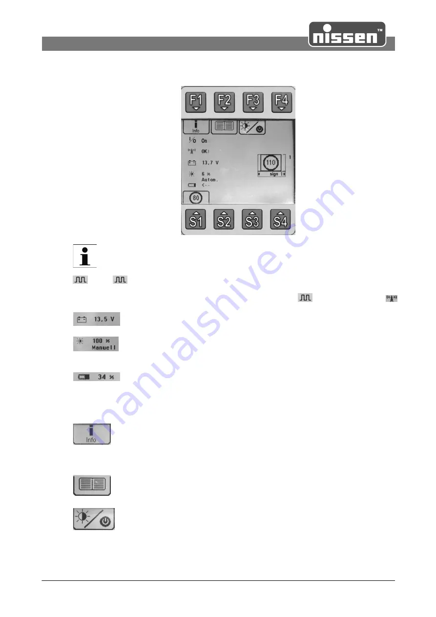
Main menu


The symbol displayed on a warning panel or an LED panel can vary depending on the version!

 OK!  or 

 ??? indicates the status of the data connection between the remote control and

SpeedSign SMD 750. If OK is displayed, the data connection has been established. If ??? is displayed,
the data connection is faulty. In the case of radio remote controls, the 

 symbol is replaced by 

.

Indicates the battery voltage of the LED panel.

Indicates the brightness of the SpeedSign SMD 750 in %. In systems with a tunnel
dimmer, reference is also made to the status of the light-sensitive switch (automatic or
manual).

Battery symbol for remote controls with radio. This symbol indicates the status of the
battery integrated in the remote control, each line that appears on the symbol
represents approx. 20% battery capacity. This value is also displayed directly behind
the symbol. An incremental symbol indicates that the battery is charging. If the battery
is indicated as a full symbol with 100% level, the charging process is complete.

The 

[F1] 

key can be used to display information, e.g. program and version number of

the remote control and the SpeedSign SMD 750. In the case of faults, information on
the type of fault is displayed here. In this case, the symbol flashes (see also "Fault
display").

The 

[F2]

 key is used to go to the Settings menu where the contrast, language, etc.

can be set (see also "Settings menu").

The 

[F3]

 key is used to switch the following functions on or off:

Dimmer function automatically/manually (optional), light arrow/variable message sign
on/off, warning lamps on/off, switching function (optional).

Summary of Contents for SpeedSign SMD 750

Page 1: ...e Sign Translation of Original Adolf Nissen Elektrobau GmbH Co KG Friedrichstädter Chaussee 4 25832 Tönning Germany Telefon 49 0 4861 6120 Fax 49 0 4861 612169 eMail export nissen de www nissen de 297087 2_en 11 2015 Operating Instructions SpeedSign SMD 750 ...

Page 2: ......

Page 3: ...erator 7 2 Personnel requirements 7 Qualifications 8 Unauthorized persons 8 3 Personal protective gear 8 4 Designated use 9 5 Special risks 10 6 Securing against being switched on again 10 7 Environmental protection 10 8 Conduct in case of danger and accidents 3 Construction and function 11 12 1 Bracket 13 2 Accessories 13 3 Remote control Eco Remote II 17 4 Remote control Standard Pro Remote II o...

Page 4: ...lektrobau GmbH Co KG 4 Index Variable Message Sign 26 1 Safety 27 2 Maintenance work 27 Cleaning 27 Maintenance of the batteries 6 Technical data 28 7 Disassembly and disposal 29 29 1 Safety 29 2 Disassembly 29 3 Disposal ...

Page 5: ...om the actual configuration 1 2 Explanation of symbols 1 2 1 Symbols used in these operating instructions Warning instructions Warning instructions are identified by symbols They are also prefaced with signal words that indicate the extent of the hazard It is essential to follow all instructions Always act cautiously during all work in order to avoid accidents injury to personnel and material dama...

Page 6: ...s are included in the sales documentation as a separate document Generally valid Alterations and technical modifications which have not been certified by Adolf Nissen Elektrobau void all warranty claims 1 5 Spare parts WARNING Risk of injury due to incorrect spare parts Incorrect or defective spare parts can lead to damage malfunction or complete failure and can greatly compromise safety For this ...

Page 7: ...rm them of the possible dangers provide the prescribed and recommended protective gear to the personnel charged with carrying out the work The operator is also responsible for ensuring that the equipment is always in a technically perfect condition is maintained according to the specified maintenance intervals and that all safety installations are checked regularly for completeness and functionali...

Page 8: ...r reflective warning clothing while working in the vicinity of railway tracks during maintenance and when securing vehicles on public roads during roadwork all personnel who are in the vicinity of public road traffic when marshalling construction traffic Dispose the reflective warning clothing after use or have it professionally cleaned to maintain visibility 2 4 Designated use The equipment is de...

Page 9: ...e cable cross section with sufficient thickness for the power consumption Make sure the earth conductor is correctly connected Protect cables and power lines against heat oil dust and aggressive media Lay cables and lines so there is no danger of tripping Do not route them along sharp edges or around pointed corners Avoid chafing kinks and crushing When using cables do not leave them wound on roll...

Page 10: ...ing instructions If hazardous substances permeate into the environment immediately initiate suitable countermeasures Immediately inform local environmental and or local authorities The following environmentally hazardous substances are used Batteries or rechargeable batteries Batteries and rechargeable batteries contain toxic heavy metals They are subject to treatment as hazardous waste and must b...

Page 11: ...poles Connect the remote control at the rear panel of the housing for switching on off SpeedSign SMD 750 or changing the display Eco Remote II Standard Pro Remote II Always switch SpeedSign SMD 750 off by using the remote control Avoid switching off by disconnecting the battery SpeedSign SMD 750 can display different speed limits CAUTION When connecting to the vehicle power supply or other electri...

Page 12: ...ty to fasten the mounting slip on type directly at the profile frame Therefore T slots are included at the rear panel By using thread T nuts optional accessories can be fastened variably and safely ATTENTION Take care of the right screw length regarding the T slots when mounting the accessories SpeedSign 750 SMD with clamps for tubes with d 60 mm standard SpeedSign 750 SMD with mounting slip on ty...

Page 13: ...l with connecting cable Eco Remote II Standard Pro Remote II Mounting slip on type for posts 40x40 mm including spacer 3 3 Remote control Eco Remote II The remote control is equipped with a graphical self luminous LCD display and a membrane keyboard The display shows the status of the system battery voltage and brightness ...

Page 14: ... switches to the display mode Cursor down This key can be assigned with a picture speed selection see menu setting speed selection Press this key until the symbolic clock has run down approx 1 sec Cursor left This key can be assigned with a picture speed selection see menu setting speed selection Press this key until the symbolic clock has run down approx 1 sec Cursor right This key can be assigne...

Page 15: ...15 Prism Sign Dimmer Automatic The brightness of the lamps is regulated automatically Manual The brightness of the lamps can be regulated manually 10 100 Speed selection only possible at function LED Matrix MultiSign The keys F1 F2 X can be assigned with a speed selection function Therefore mark the requested key with cursor and confirm with OK Select with cursor key the requested picture from the...

Page 16: ... when starting Eco Remote II select where the configuration shall be transmitted F1 Remote control stores all data from the system to the remote control F2 Master circuit lamp 1 stores all data from the remote control to the system The system is ready for operation now NOTE Upon delivery the system is configured correctly but the remote control can contain different settings Is a different configu...

Page 17: ...ight side of the display Information indicated on the left shows the status of the battery voltage brightness data connection and whether the device is switched on or off Key functions Special keys S1 S4 Fault display Remote control ON OFF Function keys F1 F4 Fault display Cursor keys Lifting key Lowering key Touchscreen display The touchscreen display enables many inputs to be made directly on th...

Page 18: ...ayed Other functions of the keys are indicated by a symbol on the display above each of the keys On key Pressing this key switches the remote control on Off key Pressing this key approx 2 seconds switches the remote control off Keeping the key pressed for longer Reset Lifting Lowering keys These keys are only used for lifting or lowering the warning board Control keys for selecting different funct...

Page 19: ... This symbol indicates the status of the battery integrated in the remote control each line that appears on the symbol represents approx 20 battery capacity This value is also displayed directly behind the symbol An incremental symbol indicates that the battery is charging If the battery is indicated as a full symbol with 100 level the charging process is complete The F1 key can be used to display...

Page 20: ...elected These are used for selecting e g warning signs lane regulation or additional texts Special key S1 leads to the submenu in which the requested symbol can be selected Special keys S2 S3 S4 are not assigned in this example The indication fields show the actual function of the corresponding special key below After pressing the requested special key the first eight preview images are indicated ...

Page 21: ...ired item with and confirm by pressing OK Adjust the brightness or contrast with and confirm by pressing OK Use the OK key to adopt the changed values Then complete the setting and leave the menu item with Esc BL display Select the brightness of the display lighting with the arrow keys and confirm with OK Setting of switch off function of display lighting S1 active lighting switches off after 1 mi...

Page 22: ...the radio remote control does not charge or no key has been pressed The Autom off function and the keys can be used to select a runtime of between 15 and 240 minutes the factory setting is 120 minutes Radio link In this setting a search is made for a Bluetooth connection that is then selected Pro Remote only Parameters Matching the remote control and system to be operated These parameters are pres...

Page 23: ...eturns to the main menu By pressing 0 or the symbol selection can be cancelled without making any changes A is indicated in the preview image when a link is established It is possible to select whether the complete link or only the indicated single symbol shall be loaded 3 4 4 Light sensitive switch Pressing the F3 function key in the main menu selects the light sensitive switch in the Pro Remote ...

Page 24: ...e charged at regular intervals see the battery symbol on the display The operating time during radio operation with the integrated battery is 12 hours As soon as the remote control is placed on the charging station it is charged by an automatic battery charger If there is a cable connection the remote control is charged via the cable connection The charge status is indicated by an incremental batt...

Page 25: ...an only be made within the applicable warranty period 4 2 Storage When not in use store the variable message sign SpeedSign SMD 750 under the following conditions Do not store outdoors protect against permanent humidity and condensate Store dirt and dust free Do not expose to aggressive media Protect against intense sun radiation Avoid long lasting mechanical vibrations Storage temperature 15 to 3...

Page 26: ... the electrical system must only be carried out by electricians Personal protective gear For maintenance work at the place of use the following protective gear is also recommended Reflective warning vest DANGER Mortal danger due to electric current Contact with live components results in mortal danger Activated electric components can carry out uncontrolled movements and cause serious injuries For...

Page 27: ...nts 5 2 2 Maintenance of the batteries NOTE The batteries supplied by Nissen together with the standard equipment are maintenance free When using other batteries it may be necessary to measure the acid level in regular periods and refill water In this case observe the instructions supplied by the battery manufacturer WARNING Battery acid When charging and handling rechargeable batteries there is a...

Page 28: ...robau GmbH Co KG Technical data Variable Message Sign 28 6 Technical data Measurements Weight approx 18 kg Operating voltage 12 V DC Power consumption approx 0 3 4 A depending on the displayed symbol and environment brightness ...

Page 29: ...live components results in danger to life Switched on electrical drives can cause components to go into uncontrolled motion and cause very serious injuries For this reason Before beginning disassembly switch off the electrical power supply Disconnect all connections from the mains 7 2 Disassembly Before beginning the disassembly Switch off the system and secure against being switched on again Phys...

Page 30: ... 2015 Adolf Nissen Elektrobau GmbH Co KG Disassembly and disposal Variable Message Sign 30 ...

Page 31: ... 2015 Adolf Nissen Elektrobau GmbH Co KG Disassembly and disposal Variable Message Sign 31 ...

Page 32: ... GmbH Co KG Printed 02 12 2015 Adolf Nissen Elektrobau GmbH Co KG Friedrichstädter Chaussee 4 25832 Tönning Germany Telefon 49 0 4861 6120 Fax 49 0 4861 612169 eMail export nissen de www nissen de Subject to technical modifications ...

Reviews: