16
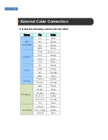
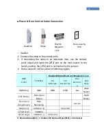
■ Power & Door Control Cable Connection
☞
Caution
①
Connect the cable to the correct ports.
②
If connecting the cable to an automatic door, use the contact
point output and open the [JP2] port on the main board. In the
factory setting, the [JP2] port is connected by the jumper.
③
Some locks do not have door monitoring signals.
LINE
Color
Function
Deadbolt/Strike/Electronic Magnetic Lock
Fail
Safe Type
Fail
Secure Type
Door
Monitorin
g
Door
Open
GND(Gray)
GND
GND
GND
NO
Open
Button
EXIT(White)
Door Open
Button
Open
Button
Door/Lock
(Blue/Brown)
Door
Monitoring
common
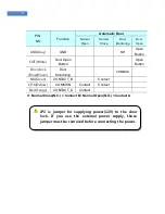
NO(Green)
CONTACT_B
VCC(12V)
COM(Yellow)
COMMON
NC(Orange)
CONTACT_A
VCC(12V)
※
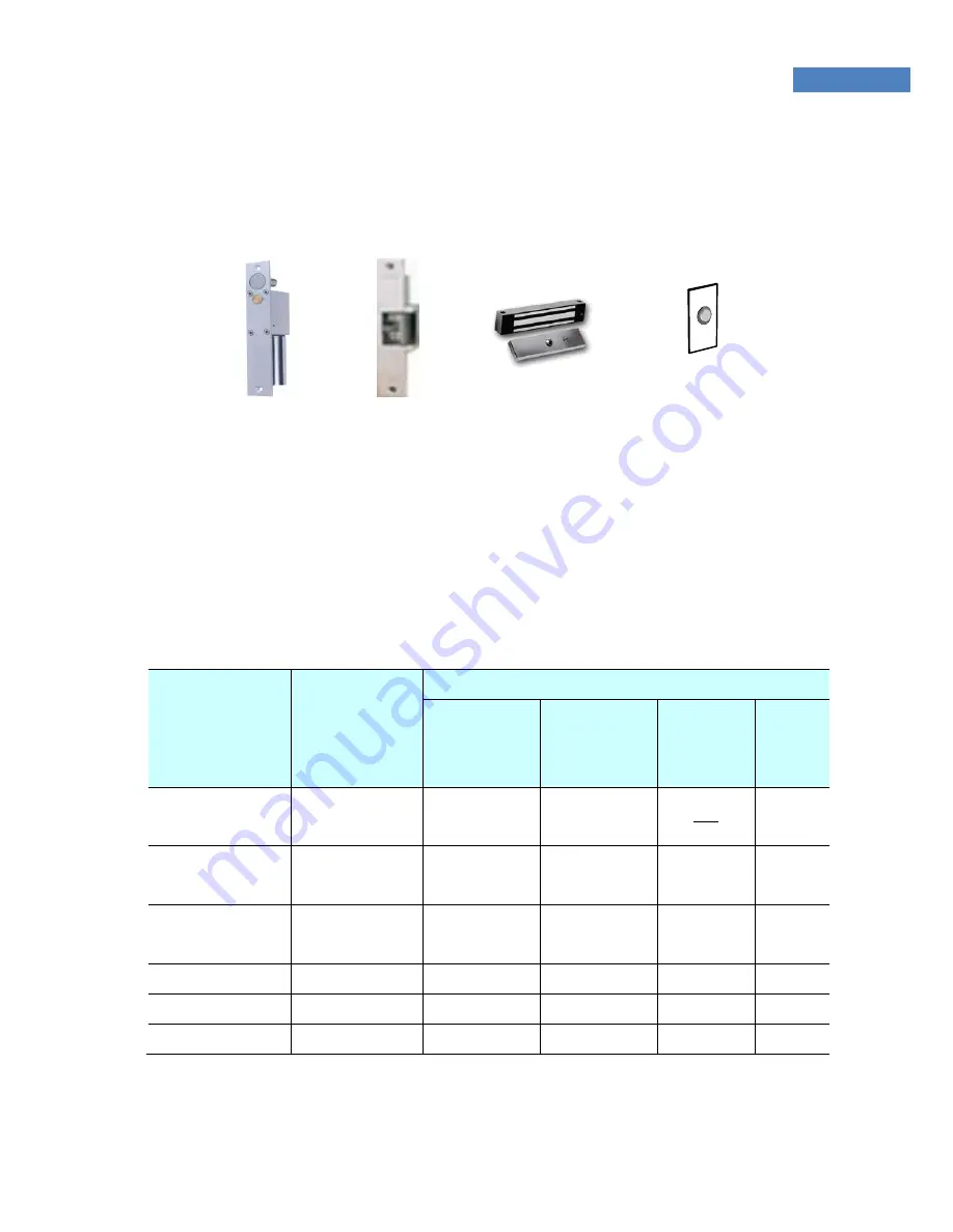
Normal Close(N.C.) = Contact B / Normal Open(N.O.) = Contact A
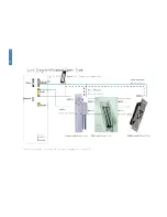
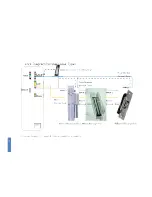
Door-opening
S/W
Deadbolt
Strike
Electric
Magnetic
Lock
Summary of Contents for Fingkey Access +
Page 1: ......
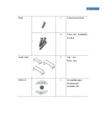
Page 4: ...4 Chapter 1 Before Installing Product Package...
Page 7: ...7 Chapter 2 Installation Environment...
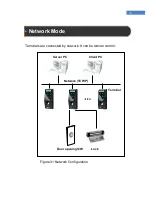
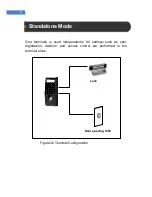
Page 9: ...Chapter 3 System Configuration Network Mode Standalone Mode...
Page 18: ...18...
Page 19: ...19...
Page 22: ...22 Chapter 5 After Installation After Installation...

