DW1401989 Rev.K2
Dec 18, 2019
1
Instruction Manual
EVA-DIP-SCI Dual Input Module
Before Installation
Please read these instructions carefully and keep for future reference.
The information in this document is subject to change without notice. For
updates please refer to our website.
Note
:
Follow the requirements for the installation of the product in
accordance with the Specifications. Otherwise it may cause malfunction.
Note
:
Do not install the product in any location where oil, dust, iron
powder, chemicals, or hydrogen sulphide may occur or affect the product. It
may cause malfunction.
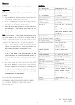
This package contains the following items:
Main unit
……………………………………………………………………
1
Outer cover EVA
……………………………………………………………
1
Instruction Manual
…………………………………………………………
1
Tapping screw
………………………………………………………………
2
Pan head screw
……………………………………………………………
2
EOL register (RE-10k)
…………………………………………………
2
General Description
EVA-DIP-SCI Dual Input Module with Short Circuit Isolator is intended
for use in addressable two wire systems. The module monitors and
transmits the status (normal, open, short, or active) of devices equipped
with NC/NO dry contacts to a control panel. The initiating device circuit
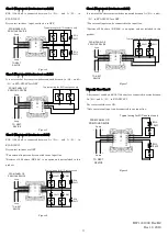
(IDC) can be wired on Class A
or Class B.
Note: Any conventional detector cannot be connected with the module.
General Operation
Normal standby condition: The module receives polling from the control
panel at the regular interval.
Polling LED (green) flashes.
Active condition: When an external input is activated, Input LED (red)
illuminates, and the module communicates to the control panel the active
status.
Trouble condition: If an overcurrent occurs because SLC (Signaling Line
Circuit) is shorted, SCI LED (yellow) illuminates, and the module
communicates to the control panel the short status. The module also
communicates to the control panel the open/short status of IDC, depending
on the Subtype Setting described below.
SCI (Short Circuit Isolator) Function
The module has a built-in short circuit isolator. SCI circuit prevents entire
loop failure in the event of a short between L+ and L- on the loop. If a short
is detected between L+ and L-, the yellow LED indicator is illuminated.
The line between Lin- and Lout- is disconnected automatically to isolate
the short circuit, and short circuit status is communicated to the control
panel. Upon removal of the short condition, the module will automatically
connect between Lin- and Lout- to restore the entire loop to the normal
standby status.
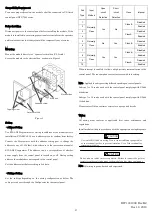
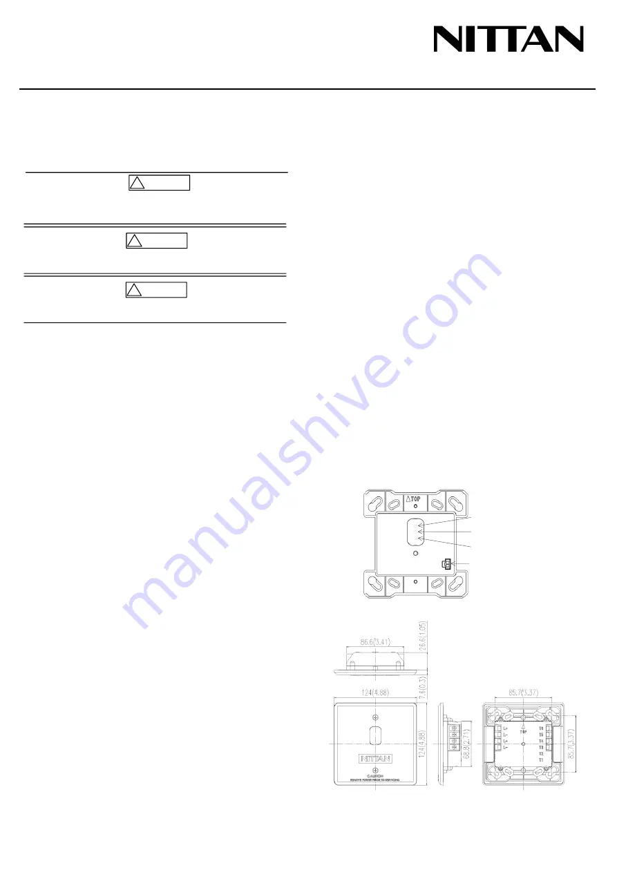
Figure 1
Figure 2
NITTAN COMPANY, LIMITED
1-54-5 SASAZUKA, SHIBUYA-KU, TOKYO 151-8535, JAPAN
http://www.nittan.com
Polling LED (GREEN)
Input LED (RED)
SCI LED (YELLOW)
Address Setting Port
mm(in)
Make sure to turn the power off before commencing any wiring work.
Otherwise it may cause electric shock or damage to equipment.
CAUTION
!
Do not use the products outside the rated power supply voltage range
specified in the Specifications. It may cause a fire or damage to
equipment.
CAUTION
!
Do not disassemble, repair, or modify the products. It may cause a fire
or electric shock.
CAUTION
!


