DW1401989 Rev.K2
Dec 18, 2019
2
Compatibility Requirement
To ensure proper operation, the module shall be connected to UL listed
control panel NFU-7000 series.
Before Installing
Disconnect power to the control panel before installing the module. If the
module is installed in an existing operational system, inform the operators
and local authorities that the system will be temporarily out of service.
Mounting
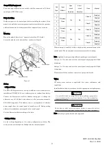
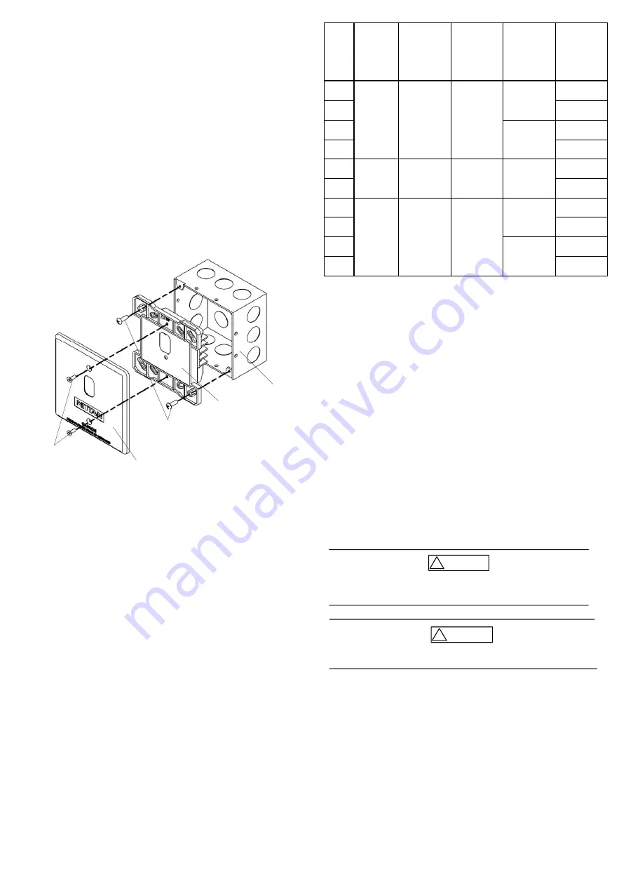
Mount the module directly to 4’’ square electrical box (UL Listed).
Secure the module to the electrical box, as shown in Figure 3.
Main unit
Outer cover EVA
Electrical box
Tapping screw
Pan head screw
Figure 3
Setting
・
Address Setting
Use EVA-AD2 Programmer for setting the address of the module prior to
installation. EVA-DIP-SCI has an address given at random from factory.
Connect the Programmer with the address setting port to change the
address to any of 1-254 (dec), with reference to the instruction manual of
EVA-AD2 Programmer. The address can be set regardless of whether
power supply from the control panel is turned on or off. During setting
address, the module does not respond to the control panel.
Set the address of module according to Job data.
・
Subtype Setting
Set the subtype depending on the wiring configuration as below. The
subtype is to be set through the Configurator for the control panel.
Sub
Type
Input
Method
Open
-
circuit
Detection
Short
-
circuit
Detection
Class
Interrupt
1
Normally
Open
Yes
No
Class B
Disabled
2
Enabled
3
Class A
Disabled
4
Enabled
5
Normally
Close
No
Yes
Class B
Disabled
6
Enabled
7
Normally
Open
Yes
Yes
Class B
Disabled
8
Enabled
9
Class A
Disabled
10
Enabled
When interrupt is enabled, it allows a high priority communication to the
control panel. The consumption current increases with this setting.
Note : Applicable subtype setting differs depending on control panels.
Subtype 1 to 10 can be used with the control panel complying with UL864
9th edition.
Subtype 7 to 10 can be used with the control panel complying with UL864
10th edition.
Please contact Nittan customer service for any required details.
Wiring
All wiring must conform to applicable local codes, ordinances, and
regulations.
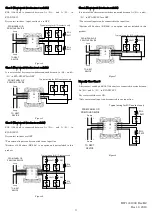
Install module wiring in accordance with the appropriate wiring diagrams.
Use cable AWG12-22 for wiring. Do not connect different gauge cables
at one terminal in order to prevent loosening. Use a fork terminal for
crimping two cables.
CAUTION
!
Do not connect cables in reverse polarity. Failure to connect the polarity
correctly could result in damage to the module and/or other equipment.
CAUTION
!
Note: All wiring is power-limited and supervised.


