DW1401989 Rev.K2
Dec 18, 2019
4
Maintenance
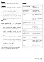
Routine inspection: Ensure the module is secure and undamaged.
Operation Test
The purpose of the Operational Test is to confirm the product’s correct
operation.
1)
When carrying out site testing of the product, the control panel shall
be set to “one-man-walk test mode” prior to the test.
2)
Take any necessary precautions to limit the sounding of the alarm
sounders/bells and any fire service summoning device.
3)
Turn on the external inputs connected to the module, and confirm
that the module is in active condition and the input LED (red)
illuminates. Confirm that an active signal is transmitted to the
control panel.
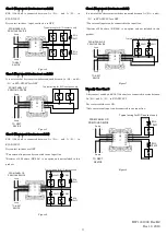
Note: If the test cannot be carried out through the external inputs, test the
area between terminal A+ and A-
(
or B+ and B-
)
to check the module. (In
accordance with the subtype setting, set the status either 0
Ω
short (for
subtype 1-4), 2.2k
Ω
short (for subtype 7-9), or open (for subtype 5-6).)
4)
After the external inputs have brought the module into the active
condition, reset the external inputs. Confirm that the module goes
back to the initial status after the external inputs are reset.
5)
If subtype is set as 1-4, or 7-10, open between terminal A+ and A-
(
or
B+ and B-
)
and confirm that the control panel detects the open
circuit. If subtype is set as 5-10, short between terminal A+ and A-
(
or
B+ and B-
)
and confirm that the control panel detects the short
circuit.
6)
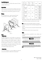
Short between terminal Lin+ (Lout+) and Lin- (Lout-), and the SCI
LED (yellow) illuminates. The short circuit isolator isolates the
devices connected after the short-circuited area, which makes these
devices have no response. Upon removal of the short condition, the
area is automatically connected to go back to the normal standby
status, and the SCI LED (yellow) turns off.
FOR WARRANTY SERVICE, RETURN TO:
OVERSEAS BUSINESS DIVISION, NITTAN COMPANY, LIMITED
1-54-5 SASAZUKA, SHIBUYA-KU, TOKYO 151-8535, JAPAN
http://www.nittan.com
Specifications
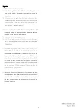
SLC Applied Voltage
Rated range 20 to 38VDC
SLC Current Consumption
Standby 3.0mA
Activated 16.9mA
(
max
)
SLC Line Impedance
Up to 50 ohms
Number of IDC Circuits
1 x Class A or 2 x Class B
IDC Circuit Rating
15VDC, 2.2k ohms, 6.8mA (max)
IDC Line Impedance
Up to 50 ohms
EOL Device
RE-10k (10k ohms, 1/4W), Class B
only
2.2k ohms EOL required for each dry
contact switch in subtype setting
7,8,9,and 10
SCI on Resistance
0.2 ohms (max)
SCI Fault Detection Threshold
10V (min)
SCI Isolation Current
22mA (max)
Visual Indicator (Status LED)
Polling LED (GREEN)
Input LED (RED)
SCI LED (YELLOW)
Ambient Installation
Temperature
0
℃
to 49
℃(
32°F to 120°F)
Storage Temperature
-20
℃
to 60
℃(
-4°F to 140°F)
Max Relative Humidity
Up to 93
%
RH, non-condensing
Environment
Indoor dry use only
Max. number of units per loop
127 units
Terminal
Screw AWG12 to 22
Address Setting
EVA-AD2 Address Programmer
Dimensions
124mm H x 124mm W x 34.5mm D
(4.882’’ H x 4.882’’ W x 1.358’’ D)
(Mount to a 4’’ square by 2
⅛
’’ deep
box)
Weight
Approximately 153g (5.4oz)
Conformity
UL864


