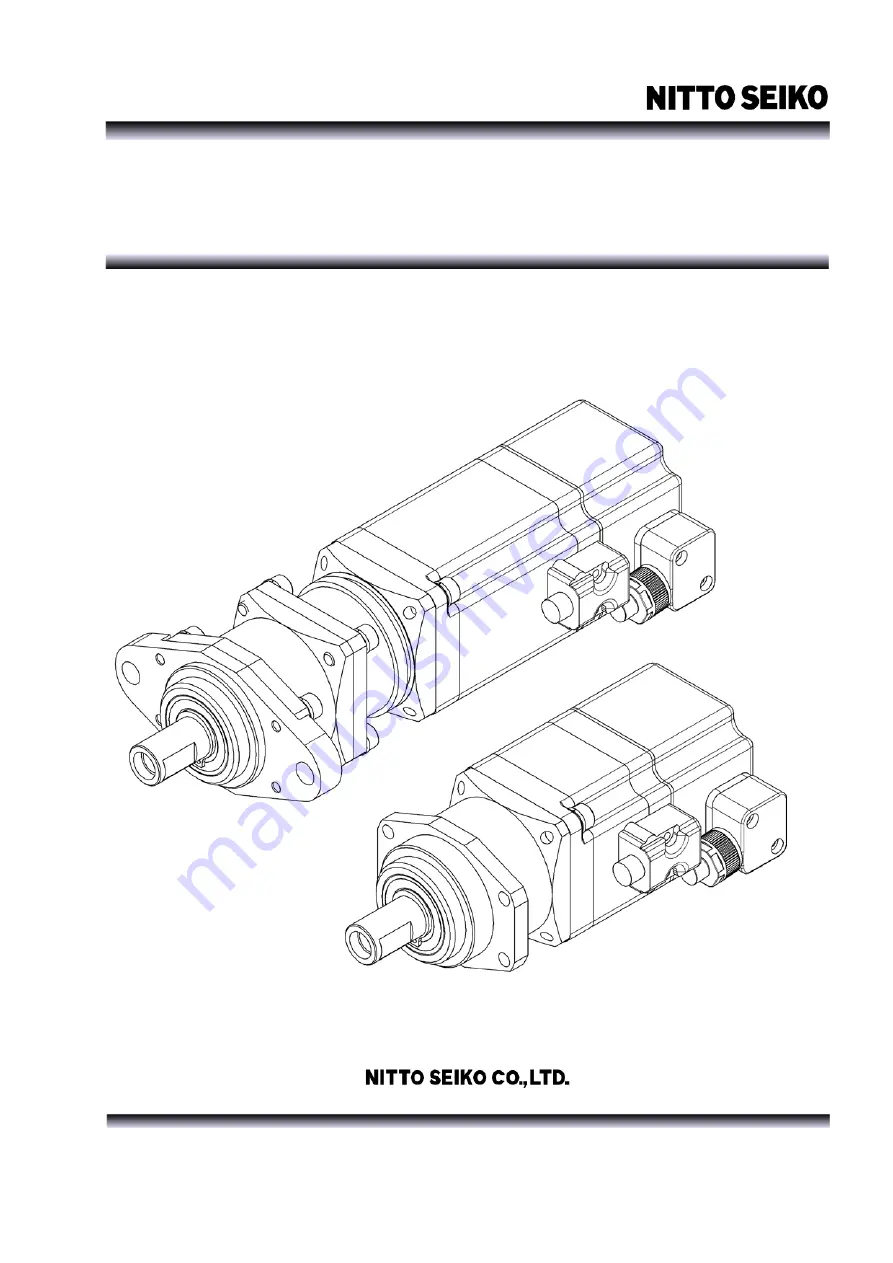
background image


Fastening  solution

<Toward a new future of manufacturing technology> 


K

K

X

X


(

(

T

T

2

2

)

)


s

s

e

e

r

r

i

i

e

e

s

s


(

(

f

f

o

o

r

r


S

S

D

D

5

5

5

5

0

0

)

)


K

K

X

X


d

d

r

r

i

i

v

v

e

e

r

r


t

t

o

o

o

o

l

l


u

u

n

n

i

i

t

t


I

I

n

n

s

s

t

t

r

r

u

u

c

c

t

t

i

i

o

o

n

n


m

m

a

a

n

n

u

u

a

a

l

l


V

V

e

e

r

r

1

1

.

.

1

1

0

0


Update : Jul. 7, 2017 

Summary of Contents for KX Series

Page 1: ...uture of manufacturing technology K KX X T T2 2 s se er ri ie es s f fo or r S SD D5 55 50 0 K KX X d dr ri iv ve er r t to oo ol l u un ni it t I In ns st tr ru uc ct ti io on n m ma an nu ua al l V Ve er r1 1 1 10 0 Update Jul 7 2017 ...

Page 2: ......

Page 3: ...uction manual Since the figures in the manual show typical examples the products you have received may differ from the figures The Instruction manual may be changed as appropriate due to product modification and improvement of ease of use of this manual If the Instruction manual is damaged or lost and you require a new one contact our agent or nearest sales office The products modified by users ar...

Page 4: ...ing precautions 6 4 Cable connection 7 5 How to change the orientation of the motor connector 8 6 Flange optional compatible with previous models 9 7 Parameter setting 10 8 Torque and output shaft rotation speed settings 12 Maintenance and inspection 24 Typical Problems and Troubleshooting 24 Appendix 25 1 Specification 25 2 External dimensions 25 ...

Page 5: ...he following items covered by CAUTION may lead to a serious accident All the items are important Be sure to follow the precautions DANGER WARNING OF F Meanings of signs Example of sign INDICATES WHAT SHOULD BE TAKEN CARE OF INDICATES WHAT MUST NOT BE DONE INDICATES WHAT MUST BE DONE Be sure to establish a ground Be sure to connect a ground terminal to the ground pole Class D ground Otherwise an el...

Page 6: ...able Don t place a heavy object on pull forcefully or twist a cable Otherwise a cable may be broken causing a fire electric shock accident or failure Don t change wiring while power is turned on Otherwise an electric shock or failure may occur Use a tool with a specified setting Since a parameter setting of a controller may vary depending on a tool unit use the controller after configuring setting...

Page 7: ...s Square type only Internal thread type and Hex type are not available 2 Square type output shaft is not available for KX050 and KX100 with gear ratio 1 1 direct coupled type 3 mark into the version number 1 7 reduction type High Torque 1 7 reduction type 1 14 reduction type Motor main body Label Model Product No Output shaft Motor cable Encoder cover Encoder cable ...

Page 8: ... t pull a cable encoder motor power supply of the tool unit Otherwise it may be broken Be sure to fix the cable when installing the tool unit 3 Don t give a strong shock to or place a load on the output shaft of the tool unit Otherwise a failure may occur Allowable loads are as follows 4 The tool unit is designed to be used indoors Use it under the following environment The motor section supports ...

Page 9: ...1 Be sure to connect a motor cable first and then connect an encoder cable Note 2 When fixing a cable be sure to hold the connector Note 3 Bending radius of the motor cable should be not less than 50 mm Note 4 Prevent the binding band and the cable etc from applying an external force to the encoder cover Otherwise the encoder may fail Note 5 In the case of the binding example 1 be sure to fix the ...

Page 10: ...change the orientation of the motor connector due to the interference Remove only the fixing screws and don t pull out the motor from the driver case Otherwise a malfunction or a failure may occur Fixing bolts M4 12 Spring washer Fixing bolts M4 12 Spring washer Models other than the one at the left side Procedure to change the orientation of the motor connector 1 Remove the hexagon socket cap scr...

Page 11: ...that of previous models If previous pitch is required for mounting attach the optional BU specification flange compatible with previous models In this case the distance between the output shaft end and the flange and the hole diameter are the same as those of previous models KX T2 Standard specification OP BU specification with previous model compatible flange KX T1 TU series Previous model Fixed ...

Page 12: ...controller SD550 Instruction manual Tool unit model Parameter number KX050T2 01 KX100T2 01 KX150T2 01 KX100T2 03 KX150T2 03 KX150T2 07 KX400T2 07 KX400T2 14 Pa 18 LP 18 0350 0350 0350 0350 0350 0350 0350 0350 Pa 60 LP 60 0001 0001 0001 0096 0096 0078 0064 0225 Pa 61 LP 61 0001 0001 0001 0029 0029 0011 0009 0016 Pa 121 LP 21 0004 0004 0003 0004 0003 0003 0003 0003 Pa 122 LP 22 0450 0348 0170 0348 0...

Page 13: ...at the same time while holding down key to change the digit to P 5 Press key to move the cursor to the right and press key to change the number of a parameter that you want to set 6 Press key to move the cursor to the right most digit 4th digit 7 If key is pressed further the setting value of current parameter is displayed Using or key change the value displayed 8 After the setting value of the pa...

Page 14: ...omes lower the rotation speed can be increased so that the time required for fastening becomes shorter However if the current is decreased too low the 2nd stage setting value takes effect in the middle of fastening before seating so that the time may be prolonged instead 2 If the rotation speed is increased too high during initial rundown a target fastening torque is exceeded because of the driver...

Page 15: ... 5 5 0 0 100 200 300 400 500 600 700 800 900 1000 出力軸回転数 rpm 衝撃トルク N m 設定電流値 10 設定電流値 20 設定電流値 30 設定電流値 40 設定電流値 50 設定電流値 60 設定電流値 70 設定電流値 80 設定電流値 90 How to read graph 2 Example When target torque is 2 0 N m Read the intersection of the horizontal line of the impact torque 2 0 N m and the Set current value Output shaft rotation speed line You can find the set current value is 70 0 0 0 5 1 0 1 5 ...

Page 16: ...t torque to 2 6 N m 87 is decided to be allowed From the graph 1 you can read that it is 900 rpm that generates an impact torque of 2 6 N m when the set current value is set to 10 Therefore set the rotation speed during initial rundown to 900 rpm The value varies depending on workpiece screw and output shaft shape etc 2 Setting final fastening set current value Rotation speed From the graph 2 set ...

Page 17: ...2 N m 4 52 N m 4 52 N m 4 52 N m 4 52 N m 4 55 N m 4 60 N m 1350 rpm 4 80 N m 4 80 N m 4 80 N m 4 80 N m 4 80 N m 4 80 N m 4 80 N m 4 80 N m 4 80 N m Graph 2 Set current value Shaft output torque comparison table Set current value Shaft output torque 10 0 46 N m 15 0 69 N m 20 0 93 N m 25 1 16 N m 30 1 39 N m 35 1 61 N m 40 1 83 N m 45 2 05 N m 50 2 27 N m 55 2 48 N m 60 2 69 N m 65 2 90 N m 70 3 ...

Page 18: ...t inertia moment I 13 145 10 6 kg m 2 Output shaft rotation speed rpm Impact torque N m Graph 2 Set current value Shaft output torque comparison table Relation between set current value and output shaft torque Set current value Shaft output torque Shaft output torque N m Set current value Set current value 20 Set current value 10 Set current value 90 Set current value 80 Set current value 70 Set c...

Page 19: ...t inertia moment I 13 145 10 6 kg m 2 Output shaft rotation speed rpm Impact torque N m Graph 2 Set current value Shaft output torque comparison table Relation between set current value and output shaft torque Set current value Shaft output torque Shaft output torque N m Set current value Set current value 20 Set current value 10 Set current value 90 Set current value 80 Set current value 70 Set c...

Page 20: ...t inertia moment I 13 145 10 6 kg m 2 Output shaft rotation speed rpm Impact torque N m Graph 2 Set current value Shaft output torque comparison table Relation between set current value and output shaft torque Set current value Shaft output torque Shaft output torque N m Set current value Set current value 20 Set current value 10 Set current value 90 Set current value 80 Set current value 70 Set c...

Page 21: ...t inertia moment I 13 145 10 6 kg m 2 Output shaft rotation speed rpm Impact torque N m Graph 2 Set current value Shaft output torque comparison table Relation between set current value and output shaft torque Set current value Shaft output torque Shaft output torque N m Set current value Set current value 20 Set current value 10 Set current value 90 Set cCurrent value 80 Set current value 70 Set ...

Page 22: ...ft inertia moment I 13 145 10 6 kg m2 Output shaft rotation speed rpm Impact torque N m Graph 2 Set current value Shaft output torque comparison table Relation between set current value and output shaft torque Set current value Shaft output torque Shaft output torque N m Set current value Set current value 20 Set current value 10 Set current value 90 Set current value 80 Set current value 70 Set c...

Page 23: ...t inertia moment I 13 145 10 6 kg m 2 Output shaft rotation speed rpm Impact torque N m Graph 2 Set current value Shaft output torque comparison table Relation between set current value and shaft output torque Set current value Shaft output torque Shaft output torque N m Set current value Set current value 20 Set current value 10 Set current value 90 Set current value 80 Set current value 70 Set c...

Page 24: ...N m Set current value Shaft output torque comparison table 70 80 90 Set current value 10 20 30 40 50 60 0 5 10 15 20 25 30 35 0 100 200 300 400 500 600 700 800 Impact torque N m Output shaft rotation speed rpm Relation between Output shaft rotation speed Impact torque comparison table Hexagonbolt PW Thickwasher M8 Weight Bit shaftinertiamoment I 2 5 10 5 kgm2 0 5 10 15 20 25 30 0 20 40 60 80 100 S...

Page 25: ...0 衝撃トルク値 N m 出力軸回転数 RPM 出力軸回転数と衝撃トルクの関係 データ測定条件 M10六角ボルト 平座金 ハードジョイント 出力軸慣性モーメントI 2 5 10 5 kgm2 データ測定条件 M10六角ボルト 平座金 ハードジョイント 出力軸慣性モーメントI 2 5 10 5 kgm2 データ測定条件 M8六角ボルト 平座金 ハードジョイント 出力軸慣性モーメントI 2 5 10 5 kgm2 70 10 20 30 40 50 60 80 90 Set current value 0 10 20 30 40 50 60 70 0 50 100 150 200 250 300 350 400 Impact torque N m Output shaft rotation speed rpm Relation between Output shaft rotation spe...

Page 26: ...t is not necessary to replace grease in short intervals However the durability of machine parts such as gear section is increased if the grease is replaced with new every 3 years In that case ask us for overhaul at your cost Typical Problems and Troubleshooting Typical problems and troubleshooting methods are explained in this paragraph For electrical problems and problems with the controller plea...

Page 27: ...ad on the end of output shaft 0 08 0 15 0 30 0 45 KX100T2 01 20 3000 550 0 16 0 3 0 6 0 91 KX150T2 01 20 3000 650 0 24 0 6 1 0 1 22 KX100T2 03 20 1360 660 0 5 1 0 2 0 2 6 KX150T2 03 20 1360 760 0 8 2 0 3 2 3 8 KX150T2 07 20 635 870 1 6 3 2 7 0 8 2 KX400T2 07S1 20 840 2100 5 0 7 0 20 24 KX400T2 14S1 20 420 2900 9 0 20 40 45 2 External dimensions KX050 150T2 1 2 1 2 KX050T2 01 20 130 133 97 5 100 5 ...

Page 28: ...the end of output shaft OP BU specification with a flange compatible with previous models Width across flats Depth 11 Output shaft M8 specification Output shaft Hexagon socket specification 6 35H Output shaft Square shaft specification 9 5 ...

Page 29: ...KX driver tool unit 27 KX400T2 Type A mm B mm KX400T2 01S1 20 224 1 189 1 KX400T2 07S1 20 251 2 216 2 ...

Page 30: ... Machinery Division http www nittoseiko co jp ...

Reviews: