8
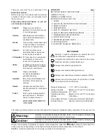
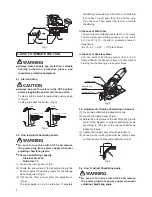
Remember that chamfering level changes depending
on the radii in this case.
Fig.13
Plate D
Min.12
Fig.14
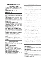
6. HOW TO REPLACE INDEXABLE INSERT
WARNING
●
Be sure to turn the switch OFF and remove
the power plug from power supply whenever
replacing Indexable Insert.
●
The Indexable Insert and the Holder are much
heated right after the operation. Always wear
gloves in handling the Indexable Insert and the
Holder.
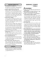
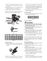
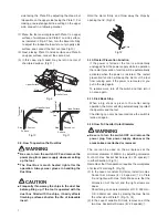
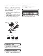
(1) Lay down the Knob with it pulled up. (Fig.15, 16)
(2) Open the Lock Plate with the Knob laid down.
(Fig.17)
(3) Remove the Indexable Insert Set Screw using the
Spanner T-15D attached to take off the Indexable
Insert. (Fig.17)
(4) Mount a new Indexable Insert (including use of
reverse surface) paying attention to the direction of
the IndeXable Insert. (Fig.17)
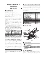
(5) Close the Lock Plate with the Knob laid down and
lay the Knob aside to lock it. (Fig.18)
PULL
UP
Knob
Fig.15
LAY
DOWN
Fig.16
OPEN
Lock Plate
Indexable Insert
Indexable Insert
Set Screw
Fig.17
CLOSE
①
PUSH
②
Fig.18
7. MAINTENANCE AND INSPECTION
WARNING
●
Be sure to turn the switch OFF and remove
the power plug from power supply during
maintenance and inspection.
●
Perform periodic inspection to check for
loosening of the attachment screws for each
part. Retighten loose screws as required.
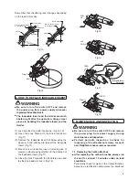
7-1. Replacing the Carbon Brushes
●
After replacing the carbon brushes, always run
the unit for at least 10 minutes under no load
conditions.
Periodically check for wear on the Carbon Brushes,
because as rectification deteriorates the likelihood
Plate D
A
φ
200
〜φ
300
Hex. Nut M8
①
Hex. Socket Set Screw
8
×
25 special
①
A
Hex. Socket Set Screw
8
×
25 special
①
Hex. Nut M8
①
Dimension
Ball Shape
Min.
φ
300
A
A
Plate D
Summary of Contents for EMB-0307B
Page 13: ......


