background image

1. Important Safety Warning 

Important safety instructions 

– Save these instructions 

Please comply with all warnings and operating instructions in this manual strictly. Save 

this manual properly and read carefully the following instructions before installing the unit. 

Do  not  operate  this  unit  before  reading  through  all  safety  information  and  operating 

instructions carefully 

There  exists  dangerous  voltage  and  high  temperature  inside  the  UPS.  During  the 

installation,  operation  and  maintenance,  please  abide  the  local  safety  instructions  and 

relative  laws,  otherwise  it  will  result  in  personnel  injury  or  equipment  damage.  Safety 

instructions in this manual act as a supplementary for the local safety instructions. Our 

company will not assume the liability that caused by disobeyingsafety instructions. 

1-1 Transportation 

  Please transport the UPS system only in the original package to protect against shock 

and impact.   

1-2 Preparation 

  Condensation  may  occur  if  the  UPS  system  is  moved  directly  from  cold  to  warm 

environment. The UPS system must be absolutely dry before being installed. Please 
allow at least two hours for the UPS system to acclimate the environment.   

  Do not install the UPS system near water or in moist environments.   

  Do not install the UPS system where it would be exposed to direct sunlight or near 

heater.   

  Do not block ventilation holes in the UPS housing.   

1-3 Installation 

  Do  not  connect  appliances  or  devices  which  would  overload  the  UPS  system  (e.g. 

laser printers) to the UPS output sockets.   

  Place cables in such a way that no one can step on or trip over them.   

  Do not connect domestic appliances such as hair dryers to UPS output sockets.   

  The UPS can be operated by any individuals with no previous experience.   

  Connect the UPS system only to an earthed shockproof outlet which must be easily 

accessible and close to the UPS system.   

  Please use only VDE-tested, CE-marked mains cable (e.g. the mains cable of your 

computer) to connect the UPS system to the building wiring outlet (shockproof outlet).   

  Please  use  only  VDE-tested,  CE-marked  power  cables  to  connect  the  loads  to  the 

UPS system.   

  When installing the equipment, it should ensure that the sum of the leakage current of 

the UPS and the connected devices does not exceed 3.5mA.   


Summary of Contents for NUPS23 Series

Page 1: ...s Niveo Professional True Sine Wave Double Conversion Online Rack Tower UPS NUPS23 1000 1 0KVA 900W NUPS23 2000 2 0KVA 1800W NUPS23 3000 1 0KVA 2700W More information WWW NIVEOPROFESSIONAL COM INFO NI...

Page 2: ...this guide 4 2 Installation and setup 4 2 1 Unpack checking 4 2 2 Real panel view 4 2 3 LCD control panel 6 2 4 Setup the UPS 6 3 Operations 8 3 1 Button operation 8 3 2 LCD display 9 3 3 UPS setting...

Page 3: ...nt The UPS system must be absolutely dry before being installed Please allow at least two hours for the UPS system to acclimate the environment Do not install the UPS system near water or in moist env...

Page 4: ...ies and verify that no current is present and no hazardous voltage exists in the terminals of high capability capacitor such as BUS capacitors Only persons are adequately familiar with batteries and w...

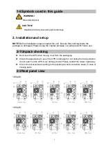
Page 5: ...ease keep the original package in a safe place for future use 2 1Unpack checking Don t lean the UPS when moving it out from the packaging Check the appearance to see if the UPS is damaged or not durin...

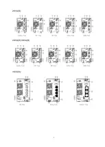
Page 6: ...5 2KVA S 2KVA H 3KVA H 3KVA S...

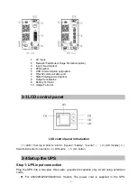
Page 7: ...erminal 10 Output Terminal 2 3LCD control panel LCD control panel introduction 1 LED from top to bottom alarm bypass battery inverter 2 LCD display 3 Selectbutton enter to next item 4 Off button 5 On...

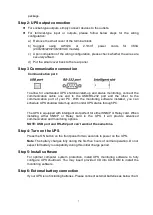
Page 8: ...ftware installed you can schedule UPS shutdown start up and monitor UPS status through PC The UPS is equipped with intelligent slot perfect for either SNMP or Relay card When installing either SNMP or...

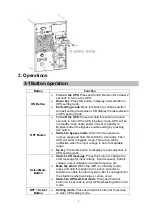
Page 9: ...is normal press and hold this button for 2 seconds Then UPS will enter to bypass mode This action will be ineffective when the input voltage is out of acceptable range Up key Press this button to disp...

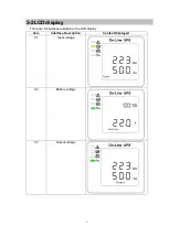
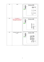
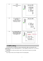
Page 10: ...9 3 2LCD display There are 8 interfaces available in the LCD display Item Interface Description Content Displayed 01 Input voltage 02 Battery voltage 03 Output voltage...

Page 11: ...10 04 Load 05 Temperature Environment Temperature Heatsink Temperature 06 Firmware Version UPS model...

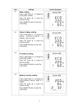
Page 12: ...as below while the charger is on 3 3UPS setting The setting fuction is controled by 3 buttons Enter Select Off up On down Enter Off up goes into the setting page Enter value adjustment Off On for cho...

Page 13: ...127 or 200 208 220 230 240 Press UP button to select the previous setting Press DOWN button to select the next setting 03 Frequency setting Press select button to change the setting 50 or 60Hz Press U...

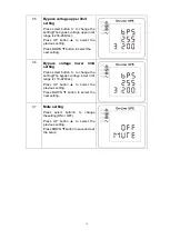
Page 14: ...lect the next setting 06 Bypass voltage lower limit setting Press select button to change the setting The bypass voltage lower limit range is 170 220Vac Press UP button to select the previous setting...

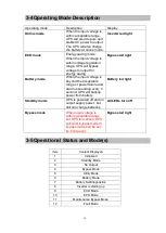
Page 15: ...he acceptable range or power failure and alarm is sounding every 4 second UPS will backup power from battery Battery led light Standby mode UPS is powered off and no output supply power but still can...

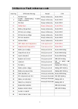
Page 16: ...ure Twice per second Fault LED lit 26 Battery over voltage Once per second Fault LED blinking 29 Output Short circuit Once per second Fault LED blinking 30 Input current limit Once per second Fault LE...

Page 17: ...ler Alarm code is shown as 34 and battery led blinking Battery voltage is too low or the charger is fault Contact your dealer Alarm code is shown as 32 and INV or BYPASS led blinking UPS is overload R...

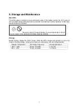
Page 18: ...ler Storage Before storing charge the UPS 5 hours Store the UPS covered and upright in a cool dry location During storage recharge the battery in accordance with the following table Storage Temperatur...

Page 19: ...cy range 40 70Hz Power factor 0 99 100 load Nominal Input Voltage Bypass voltage range Bypass high voltage point 230 264 setting the high voltage point in LCD from 230Vac to 264Vac Default 264Vac Bypa...

Page 20: ...S transfer to bypass after 1minute when the utility is normal 110 130 UPS transfer to bypass after 5 seconds when the utility is normal 130 UPS transfer to bypass immediately when the utility is norma...

Reviews: