background image

8

to the neutral setting. 

The speed system is efficient, sensitive and precise. The pilot can use the 
system whenever they want during the flight. In the neutral position the 
glider will fly at the standard speed and glide. Using full speed-bar, the 
wing will fly at maximum speed, but the glide will be adversely affected.  

•Released speed-bar: the A, B and C-risers are aligned.
•Full speed-bar: the difference between the A - C-risers becomes 160 
m/m for all sizes.

Please note!
The use of the speed system results in changes to the speed and 
reactions of the wing. For more information, please see the certification 
report.

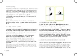
2.5.1 SPEED SYSTEM ASSEMBLY.

The speed-bar consists of the bar that the pilot pushes with their feet, as 
well as the two cords that connect it to the speed system components 
on the risers. Once you have chosen the type of speed-bar you prefer, 
you must install it. Some considerations:

• You should use the type of speed-bar you consider appropriate, 
depending on the type of harness, personal preferences, etc. 
• The speed-bar is detachable to facilitate its connection and / or 
disconnection to the risers as well as subsequent adjustment.
• To connect it to the harness, please follow the instructions of the 
harness manufacturer. The majority of harnesses have a speed system 
pre-installed. 
• The standard connection of the speed-bar to the speed system is via 
Brummel hooks, where two slots in the hooks are interlocked, making 
their connection / disconnection easy. However, any connection system 
that is safe may be used.

2.5.2  CHANGING THE RISER CORDS.

In spite of the speed system having pulleys with bearings to reduce 
friction to a minimum, the frequency with which the speed-bar is used 
causes the cord to wear and you may need to replace them.

In all Niviuk gliders the speed system cords on the risers are completely 
removable and easily replaceable.  You can use the Brummel hooks, not 
use them, remove them, use another type of connector, etc. It is even 
possible to fix the speed-bar cords directly to the speed system on 
the risers. This last option makes the connection / disconnection more 
laborious, but means the cord has maximum travel without obstructions 
or restrictions which is very useful for some models of harnesses.

2.6 INSPECTION AND WING INFLATION ON THE GROUND

After your gear has been thoroughly checked and the weather conditions 
deemed favourable for flying, inflate your IKUMA 2 as many times as 
necessary to familiarise yourself with its behaviour. Inflating the IKUMA 
2 is easy and should not require a great deal of physical effort. Inflate 
the wing with a little pressure from the body using the harness. This may 

Summary of Contents for IKUMA 2

Page 1: ...IKUMA 2 User s manual...

Page 2: ...or small details which is reflected in this new design by the NIVIUK R D team with Olivier Nef at the helm We are confident you will enjoy flying this glider and will soon discover the meaning of our...

Page 3: ...IN FLIGHT 10 4 1 FLYING IN TURBULENCE 10 4 2 POSSIBLE CONFIGURATIONS 11 4 3 ACCELERATED FLIGHT 12 4 4 FLYING WITHOUT BRAKE LINES 12 4 5 KNOT S IN FLIGHT 12 5 LOSING ALTITUD 13 5 1 BIG EARS 13 5 2 B3...

Page 4: ...safety and very forgiving flight characteristics Gliders with high collapse resistance outside normal flight Description of the skills required by the pilot to fly an EN B wing Designed for all pilots...

Page 5: ...heat or breaks Structured Leading Edge SLE the use of the SLE considerably reduces the amount of Mylar which was used in previous Niviuk wings and this also reduces the weight of the leading edge The...

Page 6: ...ollowing specific maintenance instructions as recommended by the fabric manufacturer Niviuk gliders are made of premium materials that meet the requirements of performance durability and certification...

Page 7: ...6 43 cm Size 28 44 44 cm Size 30 43 44 cm Care should be taken with the chest strap setting as the distance of the chest strap setting will affect the handling of the glider If the chest strap is too...

Page 8: ...manufacturer The majority of harnesses have a speed system pre installed The standard connection of the speed bar to the speed system is via Brummel hooks where two slots in the hooks are interlocked...

Page 9: ...consideration this extra distance during acceleration With this profile deformation there is a risk of generating turbulence and causing a frontal or asymmetric collapse 3 THE FIRST FLIGHT 3 1 CHOOSE...

Page 10: ...a pack the wing with each rod on top of the other and then fold the wing as required This folding system ensures that both the fabric and the reinforcements of the internal structure are kept in perfe...

Page 11: ...opening of the collapsed glider side Do not over brake or slow down the flying side of the wing control the turn Once the collapsed side is open make sure you return to normal flying speed Frontal col...

Page 12: ...e turn Then locate the 3STI stabilo line attached to the wing tip trapped between the other lines This line has a different colour and is located on the outside position of the B riser Pull this line...

Page 13: ...andles because there will be an increased risk of stalling the wing or entering a negative spin Before attempting to clear a knot make sure there are no other pilots flying in the vicinity 5 LOSING AL...

Page 14: ...liner wings can often prove difficult With the current 2 or 3 liner wings the inability to pull big ears or the risk involved in doing so concerns many pilots who want to have a controlled rapid desce...

Page 15: ...body With practice you will fully appreciate and understand it Only practise this manoeuvre at high altitude and with enough ground clearance To start the manoeuvre first weight shift and pull the bra...

Page 16: ...re equipped with the latest technological advances gained from the experience of our R D team Careful maintenance of your equipment will ensure continued top performance Apart from the general checks...

Page 17: ...est in this type of lines However one of the obligations derived from the use of these lines is the need to maintain the trim of your IKUMA 2 within the stipulated ranges We recommend checking the lin...

Page 18: ...u have not been properly trained to use it Do not take advice or accept any informal training from anyone who is not properly qualified as a flight instructor 9 GARANTEE The equipment and components a...

Page 19: ...19...

Page 20: ...2 1 4 3 2 1 4 3 2 1 4 3 2 1 4 3 3 1 A A B C A A B C A A B C A A B C A A B C mm 145 145 145 145 145 Kg 65 85 75 95 85 105 95 115 105 130 Kg 4 1 4 4 4 6 4 9 5 2 B B B B B 10 TECHNICAL DATA 10 1 TECHNICA...

Page 21: ...PLIER UPPER CASCADES DC 60 LIROS GMHB GERMANY UPPER CASCADES DC 40 LIROS GMHB GERMANY MIDDLE CASCADES DC 60 LIROS GMHB GERMANY MIDDLE CASCADES DC 40 LIROS GMHB GERMANY MIDDLE CASCADES A 8000 U 70 EDEL...

Page 22: ...10 3 RISERS PLAN 22...

Page 23: ...10 4 SUSPENSION PLAN 23...

Page 24: ...0 340 340 383 470 A B C D BR 1 6930 6841 6938 7021 7384 2 6882 6794 6874 6961 6965 3 6842 6754 6833 6919 6822 4 6852 6765 6862 6941 6850 5 6794 6710 6807 6885 6699 6 6761 6678 6761 6839 6538 7 6710 66...

Page 25: ...0 340 340 383 470 A B C D BR 1 7820 7716 7828 7921 8321 2 7768 7664 7756 7855 7851 3 7728 7625 7715 7812 7692 4 7741 7638 7749 7838 7726 5 7680 7579 7689 7777 7560 6 7644 7544 7637 7725 7381 7 7586 74...

Page 26: ...55 7841 6 7912 7815 7911 8001 7657 7 7856 7765 7859 7943 7620 8 7873 7784 7895 7956 7758 9 7782 7704 7788 7585 10 7686 7614 7691 7524 11 7576 7519 7595 7496 12 7544 7478 7560 7594 13 7267 7240 7258 14...

Page 27: ...A 5 A 6 A 7 A 8 A 9 A 10 B 11 A 12 A 13 A 14 B 15 A 16 A 17 A 18 B 19 A 20 A 21 A 22 A 23 A Classification B In accordance with standards EN 926 1 2015 EN 926 2 2013 and LTF NFL II 91 09 PG_1628 2019...

Page 28: ...A 3 B 4 A 5 A 6 A 7 A 8 A 9 A 10 B 11 A 12 A 13 A 14 B 15 A 16 A 17 A 18 B 19 A 20 A 21 B 22 A 23 0 Classification B In accordance with standards EN 926 1 2015 EN 926 2 2013 and LTF NFL II 91 09 PG_16...

Page 29: ...niviuk com...

Reviews: