background image

Technical Instruction  
Ex-Separator Module iXT0 

Installation and connection 


page 24  


Ex-Separator Module iXT0 - rev. 02 / 28.08.2017 


For installation in wet environments or in areas featuring the risk of flooding it 
may be necessary to install extra protective measures such as a residual cur-
rent device (RCD) if required. 


Check if the power supply of the units must be integrated into the facility's 
emergency shutdown conception. 


Transmitters and sensors shall be installed completely before feeding the 
supply voltage.  


Make sure that the installation is correct. 


The installation shall be carried out by qualified personnel only.  


Legal standards, provisions and technical regulations need to be observed. 


13.1  Connection cable 

Between sensor and transmitter 

For the complete distance between the NIVUS sensors and transmitter  
NivuFlow xxx use the cable Type  


LiYC11Y 2x1.5 mm² + 1x2x0.34 mm² + PA  

if possible. 
 

Between sensor and iXT0 

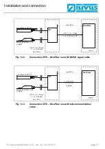
Maximum cable lengths between sensors and iXT0 if using the NIVUS standard 
cable LiYC11Y 2x1.5 mm² + 1x2x0.34 mm² + PA: 


150 meters (see Fig. 13-1) 


Use of overvoltage protection elements: 

o


Single-side: 135 meters 

o


Double-side: 120 meters 


Summary of Contents for iXT0

Page 1: ...XT0 2 nd Version Rev 02 28 08 2017 Original manual German rev 02 as of 22 08 2017 as of Firmware Version 1 10 NIVUS GmbH Im Taele 2 75031 Eppingen Germany Phone 49 0 72 62 9191 0 Fax 49 0 72 62 9191 9...

Page 2: ...0 3 88071697 info nivus fr www nivus fr NIVUS Ltd United Kingdom Wedgewood Rugby Road Weston under Wetherley Royal Leamington Spa CV33 9BW Warwickshire Phone 44 0 8445 3328 83 nivusUK nivus com www n...

Page 3: ...ountry in the European Economic Area EEA this manu al must be translated into the language of the country in which the device is to be used Should the translated text be unclear the original manual Ge...

Page 4: ...Personnel requirements 10 5 Intended use 11 5 1 User s responsibilities 13 5 1 1 Keep the manual 13 5 1 2 Provide the manual 13 6 Liability disclaimer 14 Product description 15 7 Overview and intende...

Page 5: ...Fastening the iXT0 23 13 Electrical installation 23 13 1 Connection cable 24 13 2 Wiring diagram 28 13 3 Sensor connection to Ex Separator Module iXT0 29 13 4 Connection of iXT0 to NivuFlow transmitt...

Page 6: ...serve the notes and particularly follow the warning notes and safety instructions Keep this manual in a safe place and make sure it is available for the users of this product at any time If you should...

Page 7: ...its or sensors and or are availa ble as download on the NIVUS homepage 2 Signs and definitions used Image Meaning Remark Action Step Action to be performed by you Note the numbering of action steps Ob...

Page 8: ...ediate high risk which may result in death or severe personal injury if not avoided WARNING Warning of danger to persons Indicates a possible danger with moderate risk which may result in death or sev...

Page 9: ...e waste water field the measurement system and cables may be loaded with dangerous disease germs Respective precautionary measures must be taken to avoid damage to one s health Wear protective clothin...

Page 10: ...ts Installation commissioning and maintenance shall be executed only by personnel meeting the demands as follows Expert personnel with relevant training an appropriate qualification Personnel authoris...

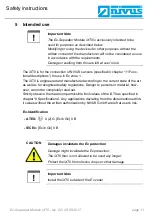
Page 11: ...is engineered and manufactured according to the current state of the art as well as to recognised safety regulations Danger to persons or material how ever cannot be completely ruled out Strictly obs...

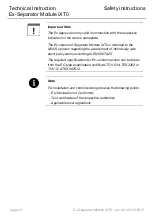
Page 12: ...or Module iXT0 is matched to the NIVUS sensors regarding the assessment of intrinsically safe electrical systems according to EN 60079 25 The required specifications for Ex version sensors can be take...

Page 13: ...serve local laws and regulations on personnel safety accident prevention regulations safety of work materials and tools safety equipment and maintenance disposal of products laws on wastes disposal of...

Page 14: ...regulations in order to avoid accidents shall be observed The safety related values of the connected iXT0 shall comply with the technical specifications or the specifications contained in the accordin...

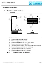
Page 15: ...3 LEDs Sensors optical voltage signal 4 Connection 2 wire sensor 1 for type 211 421 HART 5 Connection air ultrasonic sensor type OCL 6 Connection v sensor 1 water cross correlation or surface radar OF...

Page 16: ...nufacturer CE label Type labelling and series identification serial number Year of manufacture Ex label on Ex version only as mentioned in chapter 5 Intended use It is important for queries and replac...

Page 17: ...2 wire sensor Table 2 Type key of Ex Separator Module iXT0 8 Specifications Power supply 12 V DC from transmitter NivuFlow xxx For use in connection with equipment in networks up to overvoltage categ...

Page 18: ...ith RS485 interface Max values per circuit Supply Uo 10 5 V Io 640 mA Po 6 72 W RS485 Uo 4 1 V Io 105 mA Po 108 mW Ui 11 V Ii 176 mA Pi 482 mW Isolation voltage Um 253 V AC Outputs 1x transmitter conn...

Page 19: ...e delivery shall be directly reported to the headquarters in Eppingen or your local distributor in written form within two weeks Note Mistakes cannot be rectified later 9 3 Transport Protect the iXT0...

Page 20: ...uction Ex Separator Module iXT0 Construction and functions page 20 Ex Separator Module iXT0 rev 02 28 08 2017 Construction and functions 10 Enclosure dimensions Fig 10 1 Dimensions DIN rail enclosure...

Page 21: ...technical separation of the following sensors NIVUS velocity sensors POA V2 CS2 EBM Box Electronic box Mini OFR EV NIVUS level sensors OCL L1 i series sensor NivuCompact NivuBar The iXT0 intrinsicall...

Page 22: ...has been discon nected from mains power in order to minimise danger and ESD risks Disconnect the iXT0 from mains power The sensitive electronic components inside the unit may get damaged by static el...

Page 23: ...deliv ery For fastening use a DIN rail type TS35 according to EN 60715 with a mini mum length of 70 mm Fasten the rail horizontally in the intended enclosure switching cabinet by us ing at least two s...

Page 24: ...letely before feeding the supply voltage Make sure that the installation is correct The installation shall be carried out by qualified personnel only Legal standards provisions and technical regulatio...

Page 25: ...ection of 0 75 mm for power supply The maximum cable length in this case is 5 m see Fig 13 1 Use the NIVUS cable LiYC11Y 2x1 5 mm 1x2x0 34 mm PA for longer distances 5 m in switching cabinets field en...

Page 26: ...serve 0 75 2 each 6 76 100 3 each 8 101 125 4 each 10 126 150 5 each 12 151 200 6 each 14 201 250 8 each 18 250 300 10 each 22 Table 4 Number of wires when using A2Y L 2Y 12x2x0 8 Higher numbers of in...

Page 27: ...nnection iXT0 NivuFlow xxx with telecommunications cable air ultrasonic OCL L1 sensor type POA or CS2 or EBM iXT 1 2 0 34 mm PA LIYC 11Y 2 1 5 mm NivuFlow max 100 m LIYC 11Y 2 1 5 mm 1 2 0 34 mm max 1...

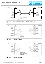
Page 28: ...x 22 GND Ex 11 S2 Rx Tx 23 S4 Rx Tx 12 S2 Rx Tx 24 S4 Rx Tx Fig 13 4 Terminal wiring diagram for iXT0 type 420 421 The X1 terminal block section is designed for connection to a NIVUS transmitter How t...

Page 29: ...or with pressure measurement cell to iXT0 2xx 4xx Fig 13 7 Radar sensor OFR to iXT0 2xx 4xx combi sensor 1 2 0 34 mm max 150 m LIYC 11Y 2 1 5 mm iXT BK shield no earth RD 9 4 V BU GN WH 8 9 10 11 12 o...

Page 30: ...e direct connection of intrinsically safe sensors Ex ib IIB optional HART I 4 20 mA A2Y 2 x 2 x 0 8 or similar max 150 m mA1 22 V Ex 1 mA1 iXT X2 1 2 3 shield if existing NivuCompact NivuBar Plus for...

Page 31: ...ronic Box EBM with water ultrasonic sensor CSM D to iXT0 4xx Fig 13 15 3 rd electronic Box EBM with water ultrasonic sensor CSM D to iXT0 4xx max 150 m LIYC 11Y 2 1 5 mm 20 21 22 23 24 X2 BK shield no...

Page 32: ...erve the notes in chapter 13 1 Connection cable as well as Fig 13 1 to Fig 13 3 Fig 13 17 iXT0 to NF750 S1 SR RD 9 4 V BU GN WH OFR 1 2 0 34 mm max 150 m LIYC 11Y 2 1 5 mm 8 9 10 11 12 outer shield su...

Page 33: ...Fig 13 18 iXT0 to NF750 M3 N7550 or 1 st iXT0 to NF750 M9 Fig 13 19 2 nd iXT0 to NF750 M9 Fig 13 20 3 rd iXT0 to NF750 M9 1 2 3 4 5 6 RxTx RxTx GND 12 V DC shield PE earth iXT X1 5 4 3 2 1 NivuFlow R...

Page 34: ...within the usual EMC limits Should you expect higher risk potentials protect the sensors by using the following combina tion DataPro 2x1 12 12 in connection with SonicPro 3x1 24 24 Note Consider the...

Page 35: ...Installation and connection Ex Separator Module iXT0 rev 02 28 08 2017 page 35 Fig 14 1 Double side overvoltage protection between iXT0 and NivuFlow 750 S1 SR...

Page 36: ...ction page 36 Ex Separator Module iXT0 rev 02 28 08 2017 Fig 14 2 Overvoltage protection sensors to iXT0 Fig 14 3 Overvoltage protection 2 wire sensor to iXT0 e g i sensor or NivuCompact or NivuBar 1...

Page 37: ...e with a dry antistatic cloth Do not use any abrasive cleansing agents 16 Dismantling disposal Improper disposal may be harmful to the environment Always dispose equipment components and packaging mat...

Page 38: ...nections First line designation of the function according to chapter 13 2 Second line TB respective clamp no on the iXT0 Third line BMP designation as used in the following EC type examination certifi...

Page 39: ...e confidential report No 14 203 142076 9 Compliance with the Essential Health and Safety Requirements has been assured by compliance with EN 60079 0 2012 EN 60079 11 2012 10 If the sign X is placed af...

Page 40: ...ion to 2 x RS485 and 1 x 2 wire sensors iXT0 211 Ex Separator Module for connection to 2 x RS485 and 1 x 2 wire sensors with 1 x HART function The permissible ambient temperature range is 20 C 40 C El...

Page 41: ...cuit Sensor supply Terminals X3 3 4 X4 3 4 X5 3 4 X6 3 4 max permissible external 119 H inductance max permissibl e external 4 2 F capacitance Ui 11 V Ii 176 mA Pi 482 mW in type of protection Intrins...

Page 42: ...mitation Additional low cost variant of the apparatus Change at some further components Change at the circuitry for HART data transmission and change of electrical data for the 2 wire analogous sensor...

Page 43: ...dditional ones TOV NORD CERT GmbH Langemarckstrar e 20 45141 Essen notified by the central office of the countries for safety engineering ZLS Iden Nr 0044 legal successor of theTOV NORD CERT GmbH Co K...

Page 44: ...T0 xxx Optional accessory Type of Protection Intrinsic Safety Marking Ex ib Gb 11B Approved for issue on behalf of the IECEx Certification Body Position Signature for printed version Date Andreas Meye...

Page 45: ...Ex Scheme Rules IECEx 02 and Operational Documents as amended STANDARDS The electrical apparatus and any acceptable variations to it specified in the schedule of this certificate and the identified do...

Page 46: ...of Issue EQUIPMENT IECEx Certificate of Conformity IECEx TUN 14 0014 2015 09 25 Schedule Issue No 1 Page 3 of 4 Equipment and systems covered by this certificate are as follows See annexe CONDITIONS O...

Page 47: ...ate of Issue IECEx Certificate of Conformity IECEx TUN 14 0014 2015 09 25 Issue No 1 Page 4 of 4 DETAILS OF CERTIFICATE CHANGES for issues 1 and above See annex I I 1 Annex _Annexe_issue 1 COC_iXT0xxx...

Page 48: ...30 EU 2014 34 EU 2011 65 EU Bei der Bewertung wurden folgende einschl gige harmonisierte Normen zugrunde gelegt bzw wird die Konformit t erkl rt in Bezug die nachfolgend genannten anderen technischen...

Reviews: