background image

Instruction Manual 
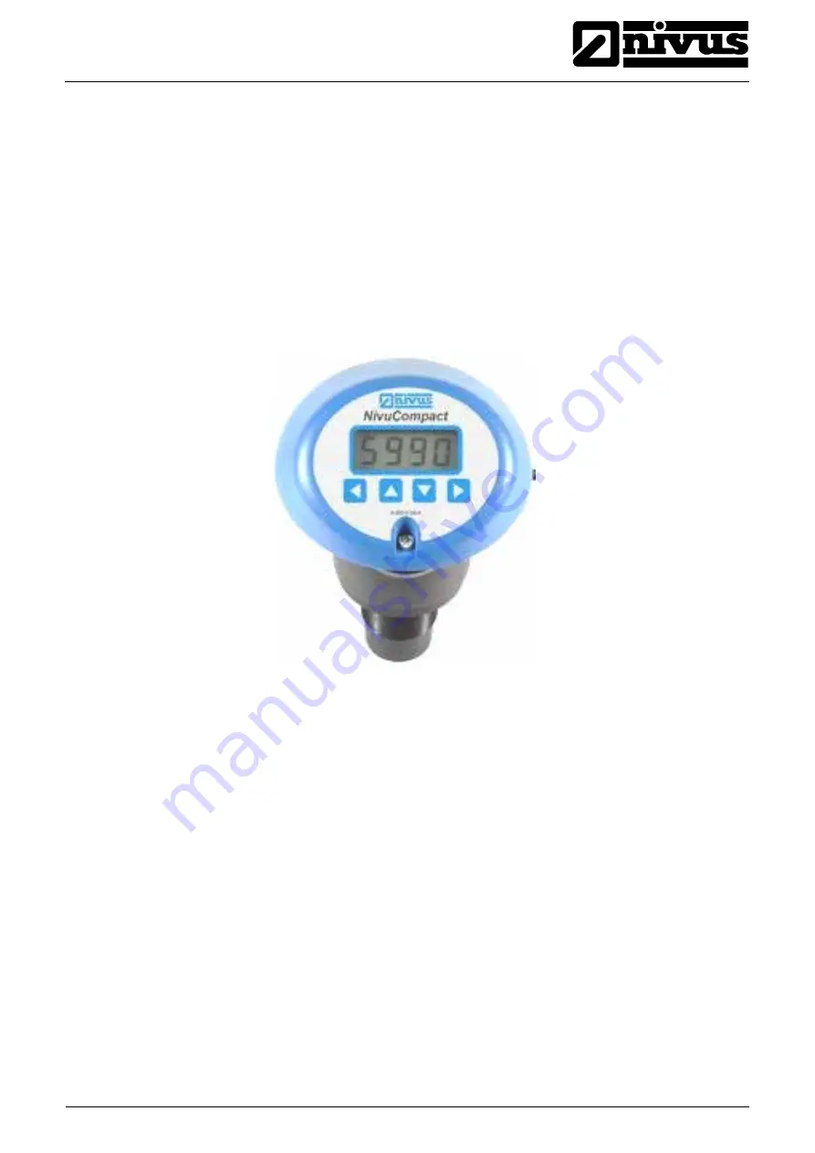
NivuCompact 


®


NivuCompact - Rev. 05 as of 31.10.2012 

page 1 


Instruction Manual for 

Ultrasonic Measurement Device NivuCompact 

(Original Instruction Manual – German) 


valid as of Software Revision No. 1.49 


NIVUS GmbH 
Im Taele 2 
75031 Eppingen, Germany  
Phone +49 72 62 - 91 91 - 0 
Fax +49 72 62 / 91 91 - 999 
E-Mail: info@nivus.com 
Internet: www.nivus.com  

Summary of Contents for NivuCompact

Page 1: ...Instruction Manual for Ultrasonic Measurement Device NivuCompact Original Instruction Manual German valid as of Software Revision No 1 49 NIVUS GmbH Im Taele 2 75031 Eppingen Germany Phone 49 72 62 91...

Page 2: ...wickshire Phone 44 0 1926 632470 E mail info nivus com Internet www nivus com NIVUS U K 1 Arisaig Close Eaglescliffe Stockton on Tees Cleveland TS16 9EY Phone 44 0 1642 659294 E mail info nivus com In...

Page 3: ...al instruction handbook German must be consulted or the manufacturer contacted for clarification Copyright No part of this publication may be reproduced transmitted sold or disclosed without prior per...

Page 4: ...inciple 13 4 1 General 13 4 2 Device Variations 14 5 Storing Delivery and Transport 14 5 1 Receipt 14 5 1 1 Delivery 14 5 2 Storing 15 5 3 Transport 15 5 4 Return 15 6 Installation 16 6 1 General 16 6...

Page 5: ...in set up menu parameter menu 28 8 3 Analog output calibration 29 8 4 Calibration Ultrasonic Measurement 30 9 Parameter list 31 10 Trouble shooting 38 11 Table of Resistiveness 39 12 Maintenance and C...

Page 6: ...NivuCompact Rev 05 as of 31 10 2012 1 2 Ex Approval The approval is only valid in connection with the respective indication on the transmitter nameplate The complete EC type examination certificate ca...

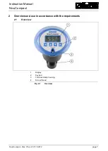
Page 7: ...on Manual NivuCompact NivuCompact Rev 05 as of 31 10 2012 page 7 2 Overview and use in accordance with the requirements 2 1 Overview 1 Display 2 Keypad 3 Terminal clamp housing 4 Screw thread Fig 2 1...

Page 8: ...as use in accordance with the requirements Damages resulting from this are left at user s risk The device is designed for a lifetime of approx 10 years After that period an inspection in addition wit...

Page 9: ...Enclosure material Valox 357x upper shell of lid to begin of thread PVDF sensor bottom and thread Temperature range process Transducer 40 C to 60 C upper shell Sensor head 40 C to 80 C sensor bottom T...

Page 10: ...ion of the NivuCompact the following information and higher legal regulations e g in Germany VDE such as applicable Ex regulations as well as safety requirements and regulations in order to avoid acci...

Page 11: ...4 XXXXX xxxx Serien Nr Jahr A 800 0226 A Fig 3 1 Nameplate of NivuCompact 3 without Ex approval XXXXX xxxx Serien Nr Jahr A 800 0269 A Ex ia IIC T4 II 1 G Sira 06ATEX2161X T 40 C to 80 C amb o o 0044...

Page 12: ...observed and adhered to In Germany the Industrial Safety Ordinance must be observed The customer must where necessary obtain any local operating permits required and observe the provisions contained t...

Page 13: ...n be set to fall to defined conditions in case of errors hold latest value 3 5 mA or 22mA If set to volume measurement the NivuCompact is capable of being used accordingly Q h using 16 break points Th...

Page 14: ...according to the delivery note for completeness and intactness immediately after receipt Any damage in transit must be instantly reported to the carrier An immediate written report must be sent to NIV...

Page 15: ...m corrosive or organic solvent vapours radioactive radiation as well as strong electromagnetic radiation 5 3 Transport Sensor and Transmitter are conceived for harsh industrial conditions Despite this...

Page 16: ...act For information on device protection see chapter 2 3 Particularly regarding Ex protection measures it must be checked if the unit power supplies must be integrated into the facility s emergency sh...

Page 17: ...Instruction Manual NivuCompact NivuCompact Rev 05 as of 31 10 2012 page 17 6 2 2 Enclosure dimensions Fig 6 1 NivuCompact 3 and 6 m Fig 6 2 NivuCompact 10 m...

Page 18: ...ht leak in An incorrect or faulty sealing does not ensure the indicated protection Connecting and or utilising the NivuCompact in another way than described in this instruction manual may interfere wi...

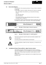
Page 19: ...nnection relays voltage output and display back lighting are not available Clamps 3 13 cannot be used during 2 wire operation 6 3 3 3 4 wire connection Fig 6 6 3 4 wire connection Terminal clamp 3 GND...

Page 20: ...A cos 0 9 6 3 4 Connection as Ex version Fig 6 7 Connection as Ex version Terminal clamp 1 12 to 28 V DC current loop input Terminal clamp 2 current loop output 4 20 mA Please observe the maximum per...

Page 21: ...t of NivuCompact Overvoltage protection is implemented by using leakage current of 20 000 A as well as automatic self control using failsafe diodes EnerPro 1 24V TR for 24 V power supply of the NivuCo...

Page 22: ...face is adjusted in a right angle to the measurement medium Fig 6 11 Correct installation of the compact echo sounder Fig 6 12 Incorrect installation of the compact echo sounder Please install the Niv...

Page 23: ...erproof cover to protect the sensor higher sensor temperatures compared to ambient temperatures will cause faulty transit time and hence faulty distance evaluation and indication 6 5 3 Installation on...

Page 24: ...e medium to be measured see Fig 6 11 If using a pipe nozzle projecting into a closed container ensure to cut the nozzle end in an angle of 45 Protect the pipe nozzle from being immersed Otherwise sedi...

Page 25: ...cient brief description of the measuring place used sensors and their positions what is to be indicated span and function of analog and relay outputs General Principles The initial start up is not all...

Page 26: ...nt P100 2 measures the distance between zero point and maximum fill level of measurement medium and indicates the value on the display P105 zero point P106 measurement span P107 near blanking distance...

Page 27: ...ell In the programming mode 1 ESC change an upper menu level or cancel a value 2 UP change to next higher parameter or increase value 3 DOWN change to next lower parameter or decrease value 4 Enter ch...

Page 28: ...application If however you input the wrong pass code the NivuCompact LC display will show Fail for 2 seconds and will revert back to operation mode To get from parameter setting menu to operation mode...

Page 29: ...the rightmost digit flashing This means that the current value is 0 The display is set to measured distance To change the display parameter to 1 press the UP key this will increase the digit by one Fi...

Page 30: ...contact NIVUS GmbH level nivus de GAS 0 C m sec ft sec Ammoniac 415 1362 Argon 308 1010 Hydrogen bromide 200 656 Chloric gas 206 676 Deuterium 890 2920 Nitrous oxide 263 863 Ethane 10 C 308 1010 Ethy...

Page 31: ...display 1 P105 Zero point 0 9999 in selected P104 unit Distance from the face of the sensor to the zero point selected in P104 unit 3 00 m 3 m 6 00 m 6 m 10 00 m 10 m P106 Measurement span 0 9999 in...

Page 32: ...depend on fill level Alarm is raised if the Failsafe Timer P809 0 P213 Relay 1 ON Setpoint Level entry 0 00 P214 Relay 1 OFF Setpoint Level entry 0 00 P220 Relay 2 Type 0 Not in use 1 Alarm 2 Control...

Page 33: ...el Shape Choice of Vessel Shape 0 600 0 Cylindrical Flat base Default P600 1 Rectangular Flat base P600 2 Cylindrical Cone base P600 3 Rectangular Pyramid base P600 4 Cylindrical Parabola base P600 5...

Page 34: ...displays the calculated volume that has been calculated using the pre set dimensions 0 0 P605 Volume units 0 No Units 1 Tons 2 Tonnes 3 Cubic metres 4 Litres 5 UK Gallons 6 US Gallons 7 Cubic feet 8 B...

Page 35: ...9 This parameter sets the distance level or space at 4 mA 0 00 P835 0 9999 This parameter sets the distance level or space at 20 mA 3 00 3m 6 00 6m 10 00 10m P838 0 9999 fine adjustment 4 mA 0 P839 0...

Page 36: ...0 StA Stability Menu Damping P870 Damping 0 9999 Enter damping at increasing level Unit P104 minute 10 0 P871 Damping 0 9999 Enter damping at decreasing level Unit P104 minute 10 0 P881 Measurement w...

Page 37: ...they all work Press the ENTER button again to test keypad You should press each button from the right to the left If the test was successful PASS will be indicated If the test was not then Err is disp...

Page 38: ...gs are correct Perform analog output test Execute reset P930 1 Faulty values on analog output Relays do not energise de energise Interface remove connected interface cable load Perform analog output t...

Page 39: ...ed below are conceived as an indication of the resistive ness of the complete moulded part In all cases we recommend to test the application under actual operational conditions Bad not resistant Fairl...

Page 40: ...ceptable aromatic Hydrocarbon acceptable Petrol gasoline acceptable weak mineral acids acceptable Sharp mineral acids acceptable weak organic acids acceptable Sharp organic acids acceptable oxygenate...

Page 41: ...ear If required clean the transmitter enclosure if with a dry lint free cloth For heavy pollution NIVUS recommends the use of surface active agents The use of abrasive cleansing agents is not allowed...

Page 42: ...3 4 wire connection 19 Fig 6 7 Connection as Ex version 20 Fig 6 8 Overvoltage Protection of 2 wire supply 21 Fig 6 9 Overvoltage Protection of analog Outputs 21 Fig 6 10 Overvoltage Protection of op...

Page 43: ...unctional Principle 13 I Initial Start up 25 Installation 16 M Maintenance 41 Maximum volume 34 N Names 3 Navigation buttons 27 Notes 10 O Operating permits 12 Overview 7 R Receipt 14 Return 15 S Seri...

Page 44: ...tre seule responsabilit la date de la pr sente signature la conformit du produit pour le march de l Union aux directives d harmonisation de la l gislation au sein de l Union 2014 30 EU Bei der Bewertu...

Page 45: ...ierte Normen zugrunde gelegt bzw wird die Konformit t erkl rt in Bezug die nachfolgend genannten anderen technischen Spezifikationen The evaluation assessed the following applicable harmonised standar...

Reviews: