background image

Nixie Tube Clock ‘Nixie QTC’ 


Issue 11a (11 December 2014)


www.pvelectronics.co.uk


- 29 - 


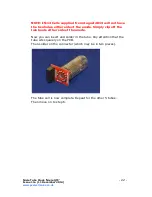
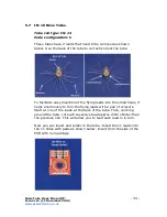
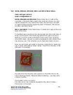
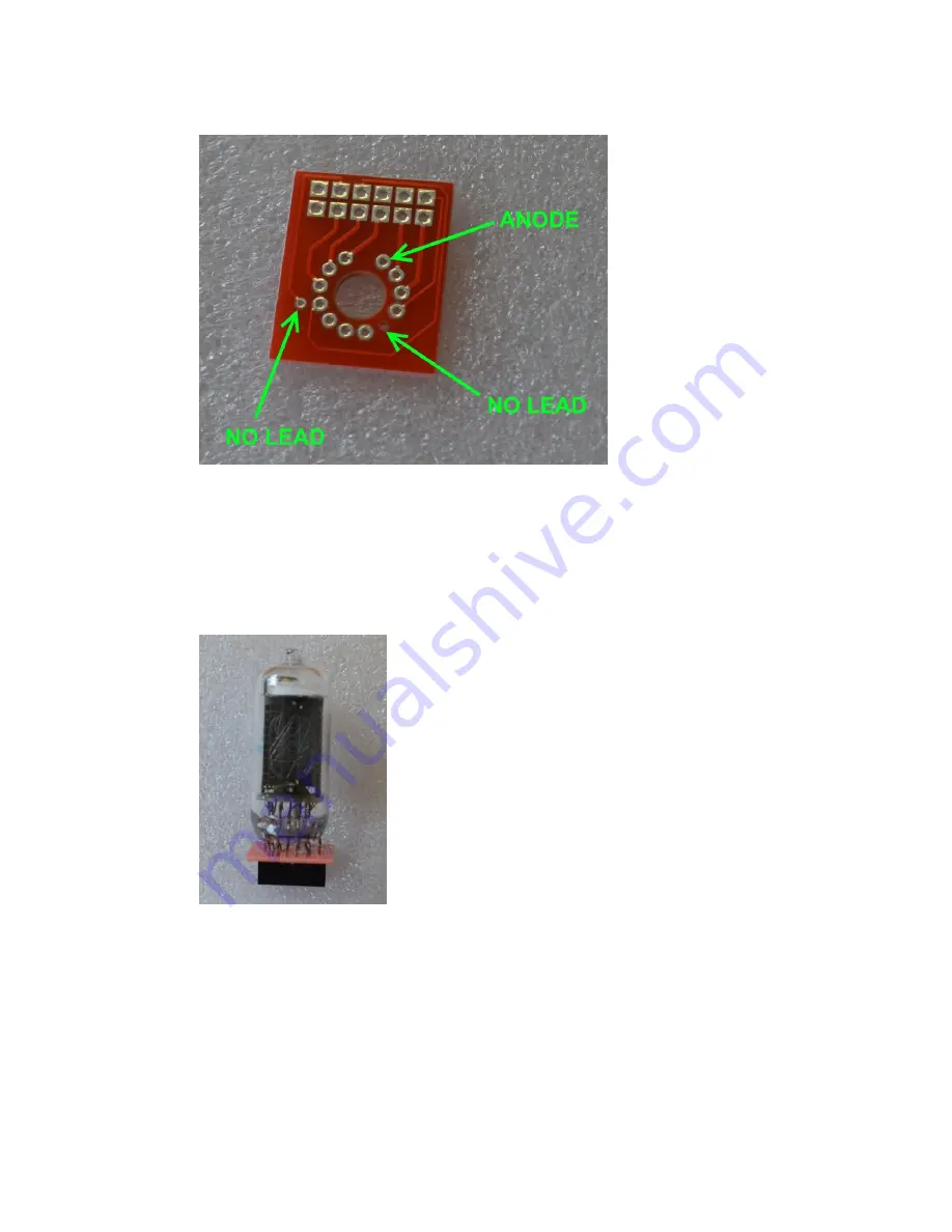
Pay attention that the tube sits squarely on the PCB. Ensure the 
tube is facing perfectly forwards before soldering - you may need 
to twist it a little.  
 
Then solder on the connector . 


The tube cell is now complete. Repeat for the other 5 tubes. 
Then move on to step 6. 


Summary of Contents for QTC

Page 1: ...Nixie Tube Clock Nixie QTC Issue 11a 11 December 2014 www pvelectronics co uk 1 Assembly Instructions And User Guide Nixie Clock Type Nixie QTC...

Page 2: ...added and code configuration procedure 9 03 April 2013 Troubleshooting connections chart added ZM1177 tube procedure clarified 8a 09 September 2013 Improved IN14 cell details 8 21 October 2012 WWVB No...

Page 3: ...A single main board is capable of driving tens of different types of solder in Nixie Tube You can even completely change the tube type of your clock by installing new tube cells and tubes Software Bu...

Page 4: ...leading zero blanking Five programmable neon colon settings Flashing AM PM indication illuminated AM PM indication both flashing both on both off Seconds can be reset to zero to precisely the set time...

Page 5: ...n the table below There are detailed and specific instructions for mounting each type of tube in sections 5 1 to 5 8 of this manual Tube types Cell type Code Configuration Section IN 14 IN 14 A 5 1 IN...

Page 6: ...s generated by this circuit can give a potentially LETHAL ELECTRIC SHOCK DISCLAIMER This product is supplied as a kit of parts intended only for suitably qualified electronic engineers who are suitabl...

Page 7: ...ill be needed to shrink the heat shrink tubing over the LEDs to form the light guides A small hair dryer may work for this 2 2 Materials you will need Solder lead tin solder is highly recommended USE...

Page 8: ...V C4 220uF 16 25V Electrolytic C5 10pF Ceramic C6 15pF Ceramic C7 100nF Ceramic C8 0 1F or 0 22F C9 C10 100nF Transistors Q1 IRFD220 MOSFET Q2 Q4 2N7000 MOSFET Q5 Q7 MPSA42 Q8 Q10 MPSA92 Q11 Q13 MPSA4...

Page 9: ...1 December 2014 www pvelectronics co uk 9 J1 2 1mm PCB power socket GPS RFT Surface mount 3 5mm jack socket LS1 Piezo sounder FUSE 500mA fuse Insulation Clear insulation for neons NX1 NX6 2X6 way 0 1...

Page 10: ...A42 6 MPSA92 3 2N7000 3 Diodes 1N5819 3 UF4004 fast recovery diode 1 62V Zener diode 2 5mm Green LED 1 5mm Yellow LED 2 5mm RGB LED 6 Integrated Circuits LM2576 5V voltage regulator 1 PIC16F1936 8 bit...

Page 11: ...s as some component bags are shared between different kit types The resistors used in the kit are 1 tolerance metal film They are marked with 4 coloured bands to identify the value However it is somet...

Page 12: ...DUE TO PRODUCT DEVELOPMENT AND IMPROVEMENTS YOUR PCB MAY NOT LOOK EXACTLY LIKE THE ONE PICTURED 4 1 Low Voltage Power components J1 FUSE D1 D3 1N5819 D4 62V Zener Diode IC1 LM2576 L2 100uH Inductor C...

Page 13: ...in the hole marked 4 2 Testing Low Voltage Power Supply Identify the test GND 5V and HV test points as shown below Plug in the power supply and then test using a DC voltmeter Touch the black probe on...

Page 14: ...Nixie QTC Issue 11a 11 December 2014 www pvelectronics co uk 14 4 3 High Voltage Generator components Socket for IC2 R1 R3 4 7 K R2 R4 390 K C3 1uF C4 220uF Q1 IRFD220 L1 100uH Inductor D5 UF4004 D9...

Page 15: ...end the leads of each resistor as shown and solder in to the correct postion making sure the component body is as close to the board as possible Take care that the notched end of the IC socket is at t...

Page 16: ...to its socket Orient the notch on the IC with the notch on the IC socket and the PCB marking Power up the PCB and using the GND and HV test points measure the high voltage generated using a voltmeter...

Page 17: ...e Tube Clock Nixie QTC Issue 11a 11 December 2014 www pvelectronics co uk 17 4 6 R6 R11 270 R5 R12 R14 R21 R28 4 7 K R15 R17 R29 R30 390 K R18 R20 10 K 4 7 Q5 Q6 Q7 Q11 Q12 Q13 MPSA42 4 8 Q8 Q9 Q10 MP...

Page 18: ...he PCB should look now 4 9 Socket for IC3 Align the notch on one corner of the socket with the marking on the PCB Be careful not to force in the socket if all pins are not aligned Ensure all pins are...

Page 19: ...RFT Connector LS1 Piezo Buzzer C8 0 1F To solder the GPS RFT connector First wet one pad on the PCB with solder Then place the connector in position and re touch the pad with the soldering iron This...

Page 20: ...en solder in place with the body of the LED just touching the PCB Then place and solder the 4 push button switches 4 13 AM PM Neon Indicators It is a good idea to install these components at the very...

Page 21: ...s into the small holes it helps enormously to trim the flying leads with a pair of scissors as shown below Start by identifying the anode lead at the back of the tube It has a white coating where it e...

Page 22: ...have the two holes either side of the anode Simply clip off the two leads either side of the anode Now you can insert and solder in the tube Pay attention that the tube sits squarely on the PCB Then...

Page 23: ...o facilitate easy insertion of the flying leads into the small holes it helps enormously to trim the flying leads with a pair of scissors as shown below Start at one of the leads at the back of the tu...

Page 24: ...Nixie Tube Clock Nixie QTC Issue 11a 11 December 2014 www pvelectronics co uk 24 The tube cell is now complete Repeat for the other 5 tubes Then move on to step 6...

Page 25: ...It is necessary to clip off two of the Z570M and equivalent tube leads Clip off the two leads as shown below This is how the tube will look after removing the leads To facilitate easy insertion of th...

Page 26: ...e tube cut each sucessive lead approx 2mm shorter than the previous one This will allow you to feed each lead in in turn Now you can insert and solder in the tube There are 11 leads on the trimmed tub...

Page 27: ...r 2014 www pvelectronics co uk 27 Insert from the side of the PCB with no markings Pay attention that the tube sits squarely on the PCB Then solder on the connector The tube cell is now complete Repea...

Page 28: ...sy insertion of the flying leads into the small holes it helps enormously to trim the flying leads with a pair of scissors Start at one of the leads at the back of the tube Then working around the tub...

Page 29: ...s co uk 29 Pay attention that the tube sits squarely on the PCB Ensure the tube is facing perfectly forwards before soldering you may need to twist it a little Then solder on the connector The tube ce...

Page 30: ...te easy insertion of the flying leads into the small holes it helps enormously to trim the flying leads with a pair of scissors Start at one of the leads at the back of the tube Then working around th...

Page 31: ...s co uk 31 Pay attention that the tube sits squarely on the PCB Ensure the tube is facing perfectly forwards before soldering you may need to twist it a little Then solder on the connector The tube ce...

Page 32: ...te easy insertion of the flying leads into the small holes it helps enormously to trim the flying leads with a pair of scissors Start at one of the leads at the back of the tube Then working around th...

Page 33: ...s co uk 33 Pay attention that the tube sits squarely on the PCB Ensure the tube is facing perfectly forwards before soldering you may need to twist it a little Then solder on the connector The tube ce...

Page 34: ...te easy insertion of the flying leads into the small holes it helps enormously to trim the flying leads with a pair of scissors Start at one of the leads at the back of the tube Then working around th...

Page 35: ...s co uk 35 Pay attention that the tube sits squarely on the PCB Ensure the tube is facing perfectly forwards before soldering you may need to twist it a little Then solder on the connector The tube ce...

Page 36: ...ate easy insertion of the flying leads into the small holes it helps enormously to trim the flying leads with a pair of scissors Start at one of the leads at the back of the tube Then working around t...

Page 37: ...tep as the microcontroller is programmed to this configuration as a factory default However it is still worth noting the procedure below in case for some reason you accidentally change the configurati...

Page 38: ...he clock should start counting 0 9 repeatedly on all tubes If this does not happen power off and check all tubes are connected correctly If the counting order is wrong go back and repeat step 6 2 Pres...

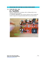
Page 39: ...HE RGB TUBE LIGHTING COMPONENTS 7 1 RGB LEDs D10 D15 Q2 Q4 2N7000 R31 R48 270 Start by installing the 18 resistors R31 to R48 and then the 3 transistors Q2 Q3 and Q4 To install the RGB LEDs first note...

Page 40: ...ck Nixie QTC Issue 11a 11 December 2014 www pvelectronics co uk 40 Then place a Nixie Tube assembly into position on the 6X2 connectors Push the RGB LED gently into position under the tube and then so...

Page 41: ...seconds will become highlighted Continue holding the button a further 2 seconds until the clock displays in this format 00 XX 99 The 99 in the seconds digits tells you that you are in the configurati...

Page 42: ...PM Indication flashing 1 AM PM Indication illuminated 2 Both flash default 3 Both illuminated 4 Both off 11 Colon neons during night dimmed mode 2 0 AM PM Indication flashing 1 AM PM Indication illum...

Page 43: ...clock reverts to normal operation 7 Date will be displayed each minute between 50 and 55 seconds past the minute 8 Press SET briefly during Night Mode to show time for prescribed period 9 Set this pa...

Page 44: ...T again to revert to normal clock operation Showing Date From time display mode briefly press SET button Date will be shown for 5 seconds then revert to time display Auto Date Display Setting paramete...

Page 45: ...overridden however the system will re set the DST status again at the next valid time sync Note that GPS time data does not contain DST information so the DST status will need to be set manually in G...

Page 46: ...lour cycling effect at your choice of speed 9 1 Entering RGB LED menu Press and hold the DST button until the display shows 00 0 00 NX3 will not be lit For each hour 0 23 you can set a custom colour E...

Page 47: ...ronics co uk 47 Colours are displayed live during RGB menu In the example above between 11 and 12 hours the LEDs will be purple 8 red 0 green and 8 blue In the example below between 19 and 20 hours th...

Page 48: ...fied hour The speed of the cycling will then be governed by the GREEN value 0 very slow change 9 very fast change This auto colour cycling mode is explained in the picture below Red 9 therefore Auto C...

Page 49: ...set from the synchronisation source This is usually only whole hours Examples o UK is 1 hour offset from the time transmitted by the DCF transmitter o France has no offset from the time transmitted by...

Page 50: ...at Anthorn UK Reception is possible within the UK Eire Northern France and Norway Please note 1 The long wave signals propagate further at night so the clock is configured by default to synchronize at...

Page 51: ...lash regularly showing the one pulse per second data from the transmitter If your Module s red LED does not start to flash regularly go back and check 1 6 of this section If the red LED does not flash...

Page 52: ...lock Nixie QTC Issue 11a 11 December 2014 www pvelectronics co uk 52 10 4 Connecting a GPS receiver The clock has been designed for and tested with our Micro GPS Receiver available separately from PV...

Page 53: ...n 2 hours and 24 hours ago and off if the last synchronisation is older than 24 hours If DCF or MSF mode is selected the indicator will flash rapidly whilst the clock is actually receiving and process...

Page 54: ...d check all connections to the HV5812 IC using the chart below Set your meter to continuity setting This is the setting where it bleeps when you touch the two probes together 11 1 Data connections fro...

Page 55: ...Nixie Tube Clock Nixie QTC Issue 11a 11 December 2014 www pvelectronics co uk 55...

Page 56: ...Nixie Tube Clock Nixie QTC Issue 11a 11 December 2014 www pvelectronics co uk 56 12 CIRCUIT DIAGRAM...

Page 57: ...Nixie Tube Clock Nixie QTC Issue 11a 11 December 2014 www pvelectronics co uk 57...

Page 58: ...Nixie Tube Clock Nixie QTC Issue 11a 11 December 2014 www pvelectronics co uk 58...

Reviews: