background image

Item 800-616-01

SuperK SPLIT

PRODUCT GUIDE

Broadband Filter

Summary of Contents for A102-200-000

Page 1: ...Item 800 616 01 SuperK SPLIT PRODUCT GUIDE Broadband Filter...

Page 2: ...ics products SuperK SPLIT Broadband filter with split VIS and NIR IR optical outputs SuperK SPLIT Broadband filter with split VIS NIR and NIR IR optical outputs Product numbers A102 200 000 A102 500 0...

Page 3: ...s the SPLIT device or accessory Target Audience This guide is for technical personnel involved in the selection planning and deployment of lasers and photonic equipment in laboratory and industrial se...

Page 4: ...d that could cause loss of data or damage the system or equipment Warning The laser safety warning alerts you to potential serious injury that may be caused when using a laser with the accessory Revis...

Page 5: ...eatures 14 Output 14 Interlock 14 Shutters 14 Interfaces 14 Top panel 14 Optical apertures 16 Electrical Interfaces 17 Status LEDs 18 Chassis labels 20 2 Installation 23 Installation process 23 Genera...

Page 6: ...6 B Service and Support Information 31 Servicing 31 Opening the chassis 31 WARRANTY VOID IF REMOVED label 31 Support Contact Details 31 Online Support Web page 31 Shipping Address 32...

Page 7: ...ble 1 Status LEDs 19 Table 2 Chassis labels 20 Table 3 Optical 29 Table 4 Interfaces 29 Table 5 Mechanical dimensions 29 Table 6 Operating and storage environment 29 Table 7 Safety and regulatory comp...

Page 8: ...8...

Page 9: ...7 Status LEDs 18 Figure 8 Side panel manufacturing label generic 20 Figure 9 Top panel labels 21 Figure 10 Partially inserting the collimator 24 Figure 11 Collimator alignment key and slot 24 Figure 1...

Page 10: ...10...

Page 11: ...11 PROCEDURES Procedure 1 Inserting a SuperK output collimator 24...

Page 12: ...12...

Page 13: ...range and the other channel consisting of a broadband subset in the NIR and infrared IR range Figure 2 SuperK SPLIT functional view Note See Table 3 on page 29 for SuperK SPLIT model specifications O...

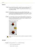
Page 14: ...circuit is broken such as an interconnected safety door switch Refer to Electrical Connections on page 25 Shutters As a safety feature each optical output of the SuperK SPLIT is equipped with a mechan...

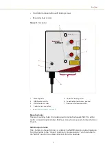
Page 15: ...IR IR output shutter This shutter can be set to block or unblock the NIR IR emission output aperture Turn the shutter to the Closed position to block emission Turn the shutter to the NIR IR position t...

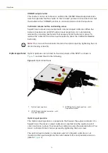
Page 16: ...he optical input by tightening the col limator locking screw 5 Optical apertures Optical apertures are located on the side panels of the SPLIT as shown in Figure 5 and described in the following Figur...

Page 17: ...l Interfaces and optical input External bus port The External bus port connects the accessory to a SuperK laser SuperK lasers connect to accessories using the NKTP External bus protocol The bus carrie...

Page 18: ...us ports and shown in Figure 7 The emission LED is lit ON RED when the connected SuperK laser s emission is enabled When ON RED laser emission is present at the primary and auxiliary optical output po...

Page 19: ...utput ports The position of the mechanical shutters at each output port does not change the status of the emission LED i Warning SuperK emissions are rated Class 4 OFF Emission disabled Power ON GREEN...

Page 20: ...tion Class 4 Laser Classification Top Safety information indicating the laser emission radiation class and precautions to take when the laser is operating Laser Aperture Top Safety information alert i...

Page 21: ...21 Chassis labels Figure 9 Top panel labels 1 Laser Aperturei i NOTE Laser apertures are located on the side panel below the label 3 Class 4 Laser Radiation Warning 2 Laser Radiation Warning 1 2 3 1...

Page 22: ...Chassis labels 22...

Page 23: ...position 4 Insert the SuperK output collimator into the Optical Input receptacle See Optical Connections on page 24 5 Using an external bus cable connect the External Bus port of the SuperK laser to t...

Page 24: ...24 laser may result in hazardous radiation exposure Warning To operate these systems you must be familiar with laser safety regulations and have received instruction in the safe use of lasers...

Page 25: ...PLIT at its final operating location and securing it to a suitable mounting surface 3 Partially insert the laser s output collimator barrel into the Optical Input receptacle as shown in Figure 10 Figu...

Page 26: ...shown in Figure 12 using a 2 5 mm hex key allen key Figure 12 Collimator lock screw Electrical Connections External bus Connect the External bus of the SuperK laser to the Bus Input of the SPLIT To c...

Page 27: ...not terminate the External bus with an NKT Photonics bus defeat er the interlock circuit remains open and laser emission cannot be enabled Adding additional accessories 1 If any additional accessories...

Page 28: ...er the power supply and the door switch interlock must be connected Refer to the instruction manual for the Su perK laser system for more information Note All bus cables used with the SuperK Extreme l...

Page 29: ...erating Temperature 18 C to 28 C 64 F to 82 F Storage Temperature 20 C to 50 C 4 F to 122 F Operating Humidity non condensing 20 to 80 Operating Altitude 3000 m maximum Operating Air Pressure 700 hPa...

Page 30: ...30 Figure 16 Mechanical dimensions 2...

Page 31: ...in your facility Opening the chassis There are no user serviceable components inside the accessory chassis Should your accessory malfunction and it cannot be serviced on site it must be shipped to the...

Page 32: ...Support Contact Details 32 Shipping Address NKT Photonics A S Blokken 84 DK 3460 Birker d Denmark 2...

Page 33: ...SuperK SPLIT Product Guide Release 1 1 01 2021 W 10456...

Reviews: