101
Connecting the optical output
Output trigger
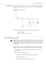
When the trigger feature is set as an output, the trigger pin should be connected
to an external pull-up resistor. The diagram
shows the trigger output
circuit.
Figure 64
Trigger output circuit
The high and low voltage levels are defined by the following equations:
Vhigh = Vexternal
Vlow = Vexternal x 22k / (22k + R)
Connecting the optical output
Caution:
Before connecting the optical output connector, ensure to check the
connector tip using a fiber microscope. Using the microscope, check for any de-
formities, damage, residue or other contaminants at the optical tip of the connec-
tor. Either clean the connector or contact NKT Photonics support if a replacement
is necessary.
The fiber and its connectors are inspected and sealed in a clean environment
before shipping. For optimum system performance, follow the guidance below:
•
Avoid removing any connector caps when the outputs are not in use and
kept in storage.
•
When connecting an output fiber, avoid:
•
Excessive strain on the fiber through stretching or twisting.
•
Fiber bend diameters < 10 cm
•
Exposing the fiber and its facets to contaminants.
Summary of Contents for ADJUSTIK
Page 1: ...Item 800 611 01 Koheras ADJUSTIK HP PRODUCT GUIDE Low Noise Single Frequency Laser System...
Page 6: ...6...
Page 12: ...12 External bus 111 D CONTROL Software 113 Installing CONTROL 113 E Part Numbers 119...
Page 14: ...14...
Page 18: ...18...
Page 20: ...20...
Page 22: ...22...
Page 38: ...Laser features 38...
Page 50: ...50...
Page 58: ...Menu items 58...
Page 90: ...Application log 90...
Page 92: ...92...
Page 104: ...104...
Page 108: ...108...
Page 118: ...Installing CONTROL 118...
Page 120: ...120 2...
Page 121: ......
Page 122: ...Koheras ADJUSTIK Product Guide Revision 1 1 03 2022 W 10456 Item 800 611 01...


