29
2 Mechanical Installation
Install the system either on a flat surface or rack-mounted in a standard 19 inch
rack. This section provides information on inserting modules and mounting or
placing the system to for optimal function and ensure that heat generated by the
laser is adequately dissipated.
General
The system must be installed on a level surface or rack that is free from
vibrations. The ambient temperature surrounding the system should be stable
and free from any sources that could cause temperature fluctuations. It is
important to note that temperature changes and vibrations may affect operation
of the inserted modules and result in abnormal operation.
Caution:
For reliable operation, the system and its modules should not be ex-
posed to corrosive agents or excessive moisture, heat sources or dust.
Operating
environment
•
Operating temperature range: +15° C to +60° C
•
Protection from dust (Pollution degree 2, Office environment)
•
Operating relative humidity: 0 to 70% (non-condensing)
Heat dissipation
Within the system, each inserted module generates heat during operation. The
heat generating components of the modules are thermally connected from the
backplane to the cooling fins mounted on the rear panel. When compared with
active cooling, using passive cooling fins avoids undesired phase noise affecting
the laser optical output. However, the installation must also ensure that adequate
airflow is available at the cooling fins to sufficiently dissipate the generated heat.
BOOSTIK modules
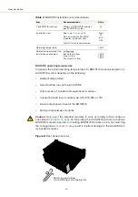
BOOSTIK amplifier modules inserted in the ACOUSTIK generate considerably
more heat than BASIK modules. To maintain the operating temperature of the
modules follow the recommendations in
.
Summary of Contents for Koheras ACOUSTIK
Page 1: ...Item 800 633 01 Koheras ACOUSTIK PRODUCT GUIDE Multi Channel Modular Laser System...
Page 10: ...10...
Page 14: ...14...
Page 16: ...16...
Page 26: ...System labels 26...
Page 28: ...28...
Page 34: ...Operating and storage environment 34...
Page 42: ...42...
Page 78: ...Module overview 78...
Page 80: ...80...
Page 82: ...82 Figure 44 Mechanical dimensions 483 00 45 00 302 50 4 50 125 00 2...
Page 92: ...Installing CONTROL 92...
Page 95: ......
Page 96: ...1 Koheras ACOUSTIK Product Guide Revision 1 0 09 2021 W 10456...


