background image


Summary of Contents for Koheras BASIK

Page 1: ...Item 800 601 01 Customer Revision 1 5 NKTP Revision 2 0 Release Date 03 2022 Koheras BASIK PRODUCT GUIDE Low Noise Single Frequency Laser Module ...

Page 2: ...PRODUCT GUIDE This guide includes the following NKT Photonics Lasers Koheras BASIK Low Noise Single Frequency Laser Module W 10456 ...

Page 3: ...port product manuals Terminology This guide may refer to the Koheras BASIK modules as the laser or as the module In specific cases where a distinction is required this guide will use the actual laser model names Target audience This guide is for technical personnel involved in the selection planning and deployment of lasers in laboratory and industrial settings The guide assumes a reasonable knowl...

Page 4: ...llation Added information and safety notices Lasers are highly dangerous devices that can cause serious injury and property damage This guide use the following symbols to either highlight important safety information or provide further information in relation to a specific topic Note Highlights additional information related to the associated topic and or pro vides links or the name of the NKT gui...

Page 5: ...ction Power mode on page 76 Updated description in section Main adapter on page 121 Added interlock jumper to Figure 74 on page 122 2022 03 1 5 Updated with the following Removed the misapplied serial monitor description and replaced it Device Monitor on page 77 Updated Table 11 on page 79 Updated Setting the operating mode on page 80 Updated Auto start on page 80 Updated Narrow and wide range set...

Page 6: ...6 ...

Page 7: ...ry of operation 24 Module variants 24 Configuration ID 24 Center wavelength 24 Output power 25 Tuning types 25 Front and rear panels 25 Front panel 25 Rear panel 26 Optical specifications 27 Laser features 27 Thermal tuning 27 Fast wavelength modulation 28 External cavity stabilization 29 Operating mode 29 Trigger 29 Auto start 29 Emission delay 30 Shutdown delay 30 ...

Page 8: ... Configuring external and internal wavelength modulation 37 Wavelength signal 38 Differential input 39 Single ended to differential 39 Singled ended input 39 Wavelength to GND 41 Differential output 42 Wavelength modulation coupling 42 Narrow versus wide modulation range 42 Frequency response 42 External cavity stabilization BASIK X15 44 Setting up external cavity stabilization 45 Section 2 OPERAT...

Page 9: ...emissions 56 Turning On the laser 56 5 Using CONTROL 59 CONTROL overview 59 Relocating panels 60 Toggling panels visible 61 Connecting to the laser 61 62 Device selector 62 Status panel 63 Status indicators 63 Module info 64 Measurements 64 WL mod button and indicator 64 Emission button 64 CONTROL settings 65 Wavelength modulation 65 Trigger 69 Power Current mode 70 Auto start 71 View 71 CONTROL m...

Page 10: ... 81 Narrow and wide range setting 81 Setting the wavelength modulation source 82 Setting the wavelength modulation signal coupling 83 Internal generator frequency 84 Internal generator amplitude 84 Internal generator signal waveform 84 Internal generator signal output 85 Wavelength modulation on off 86 Trigger setting input output 86 Trigger indicates emission 87 Trigger sawtooth wavelength modula...

Page 11: ...nnecting an interlock switch 98 Connecting power 99 Connecting modulation signals 99 BASIK interface board 99 Connecting the trigger input or output 102 Input trigger 102 Output trigger 103 Connecting the optical output 103 Appendices A Specifications 107 B Service and support Information 111 Servicing the laser 111 Opening the laser chassis 111 WARRANTY VOID IF REMOVED Label 111 Support contact d...

Page 12: ...11 Main electrical interface 113 D CONTROL Software 115 Installing CONTROL 115 E RS 485 adapter 121 Main adapter 121 F Configuration ID 123 Module Configuration ID 123 ...

Page 13: ...menu items 59 Table 10 Device Monitor parameters 77 Table 11 Generic user interface registers 79 Table 12 Power adapter specifications 99 Table 13 Wavelength modulation pin descriptions 101 Table 14 Extra I O pin descriptions 101 Table 15 Optical 107 Table 16 Mechanical dimensions 107 Table 17 Operating and storage environment 107 Table 18 Electrical 108 Table 19 Safety and regulatory compliances ...

Page 14: ...14 ...

Page 15: ...Single ended input with 2 5 V on an unused branch 40 Figure 14 Single ended input signal with GND on an unused branch 41 Figure 15 Single ended input connections with 0 V on an unused branch 41 Figure 16 Differential output signal 42 Figure 17 BASIK X15 wavelength modulation response 43 Figure 18 BASIK E15 C15 Y10 wavelength modulation response 44 Figure 19 BASIK X15 in Pound Drever Hall configura...

Page 16: ...ing the wavelength offset 80 Figure 45 Setting the operating mode 80 Figure 46 Setting the Auto start function 81 Figure 47 Setting the emission delay 81 Figure 48 Setting the modulation range parameter 82 Figure 49 Setting the wavelength modulation signal source 82 Figure 50 Setting the coupling type 83 Figure 51 Setting the internal generator frequency 84 Figure 52 Setting the signal amplitude o...

Page 17: ...ing holes and handle 96 Figure 66 Safety interlock connected to a door switch open position 98 Figure 67 Power supply 99 Figure 68 BASIK interface board 100 Figure 69 Trigger input circuit 102 Figure 70 Trigger output circuit 103 Figure 71 Mechanical dimensions 109 Figure 72 Warranty seal 111 Figure 73 Main electrical interface PIN layoutl 113 Figure 74 RS 485 adapter 122 Figure 75 How to read the...

Page 18: ...18 ...

Page 19: ...ure 3 Turning on the laser using CONTROL 56 Procedure 4 Turning on the laser using the Generic User Interface 58 Procedure 5 Relocating panels 60 Procedure 6 Using the Key Updater tool 72 Procedure 7 Using the Log Downloader 73 Procedure 8 Connecting the door interlock circuit with the RS 485 adapter 98 Procedure 9 Installing CONTROL 115 ...

Page 20: ...20 ...

Page 21: ...ts chassis types It includes the following topics Laser Description on page 23 Module variants on page 24 Main electrical Interface on page 26 Laser features on page 27 Miscellaneous on page 31 Optical interface on page 32 Laser control on page 33 Status LEDs on page 33 Module labels on page 34 ...

Page 22: ...22 ...

Page 23: ...multi channel laser system such as the Koheras ACOUSTIK for applications requiring multiple light source channels Figure 1 BASIK front panel Four variants of the BASIK are available with additional options that can be specified The variants are all designed with distributed feedback fiber laser technology and center wavelengths which can be specified from either 1535 to 1580 nanometers or 1030 to ...

Page 24: ...al Bragg grating the single mode operation is constantly maintained and is stable over the entire operating frequency band of the laser Module variants The Koheras BASIK modules are available in four variants The modules are primarily classified by their wavelength and output power Table 1 describes the key technical differences between the variants Table 1 BASIK variant specifications Configurati...

Page 25: ... Wide thermal tuning Provides a wider thermal tuning range at the expense of reduced immunity to vibration and acoustic pickup Piezo tuning If the Piezo tuning option is included the laser supports fine fast wavelength modulation For further information see Fast wavelength modulation on page 28 Front and rear panels Front panel The front panel shown in Figure 2 includes optical output fiber connec...

Page 26: ...udes the main electrical interface an alignment hole and two M4 tapped holes for fastening the laser from the rear Main electrical Interface The main electrical interface is a DIN 30 pin C 3 type connector that provides all signal and power connections to the laser Signals on the interface include Serial communication RS 485 communication signals Interlock Pins supporting a safety interlock circui...

Page 27: ...of Appendix A shows the dimensions of the laser including the alignment and screw holes positions Optical specifications Main optical output Laser emission from the output is classified as CLASS 3B The main output is identified by the laser aperture label next to it Monitor Output Emission from the optional monitor output is classified as CLASS 1 and therefore does not require a laser aperture lab...

Page 28: ...ent As this signal varies and increases its positive potential the wavelength increases Figure 4 shows the frequency response when the fast wavelength modulation feature is utilized The graph shows the response for both standard and wide thermal tuning substrates Figure 4 Frequency response using wavelength modulation The response shown in Figure 4 is for a laser with a wavelength at 1550 nm The r...

Page 29: ...re configured from the factory to oper ate in power mode Trigger A trigger logic input or output pin see Table 20 is available on the electrical interface The trigger pins can be used for two purposes To input a logic high signal that initiates laser emission To output a logic high signal that indicates laser emission For more information on connecting the trigger see Connecting the trigger input ...

Page 30: ...k enable pins See Main electrical Interface on page 26 are set to low or a disable command is sent When the laser is integrated with an amplified system the shutdown delay ensures the laser s seed signal does not disappear before an interfacing amplifier is turned off High temperature shutdown To prevent thermal run away when the laser module temperature exceeds 65 C this feature automatically shu...

Page 31: ... laser ensure to read and understand all safety statements of the document Koheras BASIK Safety Handling and Regulatory Information A paper copy of this document is included with your laser If you do not have access it you can download a copy from https www nktphotonics com lasers fibers support product manuals Accessories USB RS485 adapter kit During integration testing or otherwise an RS 485 ada...

Page 32: ...tical ports are assigned See Support contact details on page 112 Optical fibers connectors and adapters If an optical output is assigned to port A or B it can be configured with either fiber patch cords with FC APC connectors FC APC pig tail or connector adapters FC APC adapter or SC APC adapter Figure 6 shows a Koheras BASIK assigned with a fiber patch cable and FC APC connector assigned to optic...

Page 33: ...g purposes the included Labview software The platform chosen either PC or custom microprocessor must connect over the laser s RS 485 serial interface see Main electrical Interface on page 26 Section 2 includes multiple chapters describing the GUI and procedures related to controlling the laser with it Note An optional USB to RS 485 adapter is available to connect a standard PC to the laser Status ...

Page 34: ...ribed in Table 5 Figure 8 Top panel label locations LED Name Condition Description Power ON Green DC Voltage at the DC power input pins is OK ON Red DC voltage at the DC power input pins is too low Flashing Amber The module is transmitting data Off No DC power at the module power input pins Emission ON Red Laser emission is ON Off Laser emission is OFF Status ON Green The module laser frequency is...

Page 35: ...ate manufactured and regulatory compliance Product Information Top Safety label showing the emission specifications the laser is capable of Laser Radiation Warning Top Safety information alert indicating this area of the laser is near a source of dangerous laser emissions Laser Aperture Front Safety information alert indicating the location of the aperture where laser radiation is emitted from the...

Page 36: ...Module labels 36 ...

Page 37: ...ximum output power setting Fast wavelength modulation If the fast wavelength modulation option is included with the laser the output wavelength can be modulated by connecting an external varying electrical signal the laser s internal function generator or both Configuring external and internal wavelength modulation As stated above you can use the option to modulate the wavelength of the Koheras BA...

Page 38: ... longer wavelength Setting Function For CONTROL see For SDK see External wavelength modulation Sets wavelength modulation to external signal mode page 65 page 82 Internal function generator Sets wavelength modulation to internal function generator mode page 67 page 82 Modulation frequency Sets the frequency of the internal function generator The settable range is from 0 008 Hz to 100 kHz page 68 p...

Page 39: ...the wavelength modulation setting when it is not in use Single ended to differential The circuit shown in Figure 11 is an example of how to generate a differential signal from a single ended input In this example a 5 Vpp single ended input signal with a 0 V common mode voltage generates a 2x 5 Vpp differential signal with a 2 5 V common mode voltage Figure 11 Single ended to differential Singled e...

Page 40: ...ifferential 2x5 Vpp input Figure 12 Single ended input signal with 2 5 V Figure 13 shows the Wavelength pin connected to the same potential as the common mode voltage of the Wavelength signal the optical output will be modulated around its center wavelength Figure 13 Single ended input with 2 5 V on an unused branch ...

Page 41: ...d to GND and the Wavelength signal is modulated between 0 and 5 V as shown in Figure 14 the optical output is modulated above its thermally controlled wavelength Figure 14 Single ended input signal with GND on an unused branch Figure 15 Single ended input connections with 0 V on an unused branch ...

Page 42: ...the module adjusts its wavelength so the differential error signal level on the Wavelength input leans towards 0 V Narrow versus wide modulation range You can set the wavelength modulation operation to either narrow or wide range As detailed in Table 7 the operation characteristic of each range depends on the module type X15 or E15 C15 Y15 Table 7 Narrow vs wide band wavelength modulation Frequenc...

Page 43: ... narrow ranges Wide 500 MHz tuning at low frequencies with a smooth roll off to a 3 dB cut off at 300 Hz Narrow 30 MHz tuning with a slight peak at 3 kHz Figure 17 BASIK X15 wavelength modulation response E15 C15 Y10 frequency response Figure 18 shows the measured frequency response of the BASIK E15 C15 Y10 for both wide and narrow ranges Wide E15 C15 8 GHz with a 3 dB cut off at 200 Hz Y10 10 GHz...

Page 44: ...response External cavity stabilization BASIK X15 An X15 module can be locked to an external cavity to obtain less low frequency phase noise by using the Pound Drever Hall technique Figure 19 depicts a general layout of the devices in a Pound Drever Hall configuration used with an X15 module Figure 19 BASIK X15 in Pound Drever Hall configuration ...

Page 45: ... Configure the module to operate in narrow modulation range see Modulation range on page 67 4 Turn on wavelength modulation see Turning on wavelength modulation on page 68 5 Set the update interval see Integrating update interval on page 68 Once enabled the module constantly adjusts its wavelength so that the Pound Drever Hall loop results in a 0 V differential applied at the Wavelength input pins...

Page 46: ...External cavity stabilization BASIK X15 46 ...

Page 47: ...HE LASER This section describes how to manage and operate the laser and includes the chapters Communicating with the Laser on page 49 Turning ON the Laser on page 55 Using CONTROL on page 59 Software Development Kit on page 79 ...

Page 48: ...48 ...

Page 49: ...d in Table 8 Table 8 Koheras BASIK PC connection kit CONTROL software The laser is shipped with the NKT Photonics CONTROL software installer on a USB key You can also download the most recent CONTROL software from the following link https www nktphotonics com lasers fibers support software drivers The CONTROL software is capable of controlling configuring and monitoring the laser Installing the so...

Page 50: ...s run Connecting CONTROL to the laser You can manage the laser using its RS 485 serial connection connected to a PC with CONTROL installed on it You can use the NKT Photonics RS 485 connection kit including the BASIK interface board to connect the laser to the PC s USB port The kit is intended to help test the laser when integrating it with a custom system Follow the steps in Procedure 1 to connec...

Page 51: ... CONTROL window opens Click on the Connect button in the left side of the window 4 CONTROL automaticallyscans for any connected lasers and accessories available on both COM and configured Ethernet ports 5 CONTROL connects with the laser In the status panel of CONTROL the Status indicator is AMBER The indicator turns GREEN when the laser thermalization set point is reached Action ...

Page 52: ...B 15 ribbon cable connect an NKT Photonics RS 485 adapter to the 16 pin main interface connector on the BASIK interface board c Connect an RS 485 adapter to your PC using a USB A to USB B cable a To power on the laser connect the power supply to the RS 485 adapter power jack and AC mains Note Connect either a door safety switch circuit to the LEMO connection of the adapter or use the adapter defea...

Page 53: ...53 Connecting the SDK GUI to the laser 4 The Generic User Interface connects to the laser and displays the current register values Action ...

Page 54: ...Connecting the SDK GUI to the laser 54 ...

Page 55: ...municating with the Laser on page 49 3 The FC APC connector is placed so that any emissions are safely contained within the working application such as a beam dump that can absorb the emitted beam power Warning Turning on the laser emits hazardous laser Class 3B radiation Ensure to observe and implement all safety regulations warnings and cautions in this guide and the Koheras BASIK Safety Handlin...

Page 56: ...the Status indicator turns ON GREEN the laser thermalization set point is reached and stabilized Note At this point the laser Status LED should also be lit ON Green 4 a In the Control panel set the reference wavelength λ or its offset using the Wavelength or offset slider control To set it click hold and move the red slider to adjust the setting b Alternatively you can directly enter the wavelengt...

Page 57: ...ress to 1 d Click Connect CONTROL connects to the laser 1 The COM port connected should have an asterisk next to it in the list 3 a Locate register 30 Emission in the CONTROL tab b In the register s text field input 1 and press the enter button to turn on the laser 4 Click on the Error and Status tab in the right side of the window and verify the Emission indicator is lit green Note You can also c...

Page 58: ...Controlling the laser emissions 58 ...

Page 59: ...p down menus with multiple functions CONTROL menu items on page 72 Quick Connect Contains a button when clicked scans all available PC ports for connected NKTP products Connecting to the laser on page 61 Device Selector Icons representing currently connected devices click to access the device Device selector on page 62 Control Panel The Control panel contains controls for the laser For example It ...

Page 60: ...ide the main window Action 1 Left click and hold the top title bar of the panel 2 While holding the left mouse button down drag the panel to another location in the main window 3 In the new location when the background turns blue release the mouse button see Figure 21 4 Alternatively drag the panel out from the main window and release the mouse button A separate window for the panel is created see...

Page 61: ...e Welcome screen is displayed as in Figure 24 In the menu bar click the Connect drop down menu and then click on the COM port your laser is connected to Control and Status panels are displayed when the laser connects to the GUI See Connecting CONTROL to the laser on page 50 Figure 24 Welcome screen and connecting Quick connect Click the Connect button and CONTROL scans all available ports for NKTP...

Page 62: ...r each connected device Figure 26 shows the device selector for an BASIK laser If multiple lasers are detected by CONTROL click on the BASIK icon to brings up its controls To modify the ICON text see View on page 71 Figure 26 Device selector panel Click CONTROL scans for connected devices Click to select ...

Page 63: ... displays the following indicators Interlock Indicates if power is connected to the laser ON Green The interlock circuit is closed and emission is allowed ON Red The interlock circuit is open or needs a reset and emission is prohibited Status Indicates the laser s thermalization and error status ON Green The laser has reached its set point operating temperature and has stabilized Click ...

Page 64: ...ation Indicator GREEN wavelength modulation is enabled GREY wavelength modulation is disabled Note The WL mod button and indicator is only displayed by CONTROL if the wavelength modulation feature is included with the laser Emission button The Emission button turns the laser emission ON or OFF see Controlling the laser emissions on page 56 The button s indicator turns ON RED when laser emission is...

Page 65: ...dulation feature Modulation source The source signal used to modulate the wavelength is selectable Click on the Source drop down menu to select one of three source modes Internal Figure 29 wavelength is modulated using the laser s internal function generator External Figure 30 wavelength is modulated by connecting an external signal to the Wavelength pins Both Figure 31 both internal and external ...

Page 66: ...nals on page 99 or directly to the main electrical interface pins The pin assignments are described in Table 19 on page 113 For information regarding example external signal generation circuits refer to section Fast wavelength modulation on page 37 Figure 29 Wavelength modulation internal source Figure 30 Wavelength modulation external source ...

Page 67: ...k on the Coupling drop down menu arrow and select either AC or DC coupling Refer to Wavelength modulation coupling on page 42 for further information Note When using wavelength modulation with an X15 module and the modula tion Range parameter is set to Narrow the modulation signal will be AC coupled and the DC component enters a software integrating function that tunes the wavelength up or down wh...

Page 68: ...ting them to operate in External modulation mode Source Integrating update interval You can set the update interval of the software integration function with this setting The setting is intended for use with X15 modules when they are set to DC coupling and Narrow modulation range Internal generator frequency When the modulation source is set to Internal the frequency of the internal generator sign...

Page 69: ...e sawtooth signal from the internal generator enables emission on the rising edge and disable emission on the downslope of the signal The sawtooth signal is controlled from the Wavelength modulation setting page by setting Source to Internal and Type to Sawtooth Then adjust the signal using the sliders on the same page Trigger Type Output Figure 35 Output source None no voltage on pin B4 Output so...

Page 70: ...pe Output Power Current mode You can set the laser output Mode to either Power or Current as described in Operating mode on page 29 Click the menu item shown in Figure 36 to toggle the mode The Control panel automatically switches the controls displayed for the new mode ...

Page 71: ...lect the Module info checkbox to display the laser serial number firmware release number or system temperature within the status panel Select the Measurements checkbox to display the system temperature in the status panel Figure 38 View setting When checked emission is enabled upon connection of DC power Toggles whether to display the serial FW release or system temperature ...

Page 72: ... Exit to exit the CONTROL program Disconnect Click Disconnect Close All to disconnect the currently connected device from CONTROL Tools Select from one of three special tools to use with your laser Tools available are Key Updater tool on page 72 Log Downloader on page 73 Extensions Overview on page 74 Window Sets whether certain panels are visible or not Toggling panels visible on page 61 Help Dis...

Page 73: ...er tool to put the device into dedicated log download mode by enabling a collect log function Note When the collect log function is enabled it temporarily disables automatic log collection from all other devices The CONTROL interface turns gray and com munication with the laser and log collection with all other modules is disabled To download log files use the Log Downloader as described in Proced...

Page 74: ...saves the file onto the CONTROL PC If the percentage shows less than 100 the log is first collected See Collect log below Collect log Starts a dedicated log collection mode that disables all other CONTROL activity 4 If you select Save log a dialog box prompts for a filename and folder to store the log in 5 If you select Collect log the log is collected and saved in dedicated mode The CONTROL panel...

Page 75: ...nel For the Koheras BASIK the control panel can be configured to present different operating mode controls for either Power or Current mode The modes are selected by clicking on the Settings drop down menu gear icon in the status panel See CONTROL settings on page 65 The wavelength or wavelength offset can also be set in the panel Wavelength You can select to control the wavelength either by input...

Page 76: ...ither mW or dBm Figure 42 Operating mode set to power Current mode In the Current operating mode the current in the fiber pump is kept at a constant level Only the wavelength or its offset control is available in the control panel menu Operating Mode set to Power Select the wavelength control type Current Set Point Slider Power control scale set in either dBm or Wavelength offset text input field ...

Page 77: ...d Status bits The actual status bits read from the connected module Error code The actual error code read from the connected module Access Protected Locked status of the module FW Ver The device module s firmware release date Module Serial The serial number of the device module PCB Serial The device module s printed circuit board serial number PCB Ver The version of the device module s printed cir...

Page 78: ...ner Figure 43 Serial Monitor The panel is enabled by placing a check mark on the Window pull down menu next to the Application Log item To close the panel click on the upper right corner X COM Total number of communication errors with framing or protocol errors Hover over the icon to list more details Busy Total number of busy responses from the module Busy responses occur when a module receives a...

Page 79: ...0 Enabling Auto start toggle 0x31 10 hex Auto start on page 80 Emission delay control 0x3A N A seconds Setting the emission delay on page 81 Narrow and wide range toggle 0x31 1 hex Narrow and wide range setting on page 81 Wavelength modulation signal source external and or internal generator 0x31 2 4 hex Setting the wavelength modulation source on page 82 Function generator frequency 0xB8 N A Hz 3...

Page 80: ...nd then press enter Contact NKT Photonics support for more information regarding the range settable Setting the operating mode To set the Power Current mode modify bit 8 of register 0x31 When the bit is set to 0 power mode is selected and when set to 1 current mode is selected Figure 45 shows the register with the bit set to 0 meaning the laser is set to power mode Figure 45 Setting the operating ...

Page 81: ...ime in seconds and tenths of seconds into the register Figure 47 Setting the emission delay Narrow and wide range setting To configure the Modulation range setting to Wide or Narrow set bit 1 of register 0x31 where 0 sets the laser to operate in Wide range and 1 sets the laser to operate in Narrow range In the example shown in Figure 48 bit 1 is set as 1 ...

Page 82: ... 0 disabled 1 enabled Bit 4 sets external wavelength modulation where 0 disabled 1 enabled Figure 49 Setting the wavelength modulation signal source The laser supports three different signal source combinations to modulate the wavelength Below are some example 0x31 register settings for all three source settings External 0x31 set to 0504 external source wide range 0x31 set to 0506 external source ...

Page 83: ...its in the rightmost two digit positions are modified since bits 2 and 4 are in the first 8 bits of the 16 bit register Setting the wavelength modulation signal coupling To configure the signal coupling for the wavelength modulation option set bit 3 of register 0x31 Setting the bit to 0 configures wavelength modulation to use AC coupling and setting it to 1 configures it to use DC coupling Figure ...

Page 84: ...r frequency Internal generator amplitude The amplitude of the internal function generator signal is set with register 0x2B The register is a 16 bit integer you can set from 0 to 100 0 In the example shown in Figure 52 the signal is set to 20 of the maximum Figure 52 Setting the signal amplitude of the internal generator Internal generator signal waveform To change the output waveform set register ...

Page 85: ...nerator waveform Internal generator signal output To enable or disable outputting the internal generator signal on the Wavelength pins set bit 5 of register 0x31 where setting the bit to 0 disables the signal generator output and 1 enables signal generator output Figure 54 Toggling the internal generator signal output ...

Page 86: ...F and 1 means ON Figure 55 Turning ON wavelength modulation Trigger setting input output To configure the Trigger signal pin as an input or output set register 0xB4 bit 1 where 0 means input and 1 means output Figure 57 shows an example of the trigger pin set as an output Figure 56 Setting the trigger to input or output ...

Page 87: ...r emission is enabled Note Bit 4 cannot be set simultaneously with bit 2 of register 0xB4 Figure 57 Trigger set to indicate emission Trigger sawtooth wavelength modulation To configure the trigger for sawtooth wavelength modulation set bit 2 of register 0xB4 where 1 means Sawtooth wavelength modulation and 0 means OFF Note Bit 2 cannot be set simultaneously with bit 4 of register 0xB4 Figure 58 Tr...

Page 88: ...ab to view the contents of read only registers Of particular interest are registers 17 and 90 When laser emission is enabled the output power in mW and dBm is displayed in these registers respectively Figure 59 Read only registers under the Readings tab Readings ...

Page 89: ...support see Support contact details on page 112 Figure 60 Error and status tab Graphing As shown in Figure 61 you can graph the values of selected parameters by clicking on the Graph tab and selecting the parameter you want to graph To use the graphing function 1 Select the parameters to graph from the drop down menu at the left right y axis and bottom x axis of the graph 2 Modify the left right y...

Page 90: ...Graphing 90 Figure 61 Graphing tab Y axis settings X axis ...

Page 91: ...91 SECTION 3 INSTALLING THE LASER This section describes how to install the laser and includes the chapters Mechanical Installation on page 93 Connecting the Laser on page 97 ...

Page 92: ...92 ...

Page 93: ...d result in abnormal operation Caution For reliable operation the laser should not be exposed to corrosive agents or excessive moisture heat sources or dust Standalone mounting Heat dissipation The heat generating components within the module are thermally connected to a 50 by 20 mm area shown in Figure 62 on the rear panel next to the electrical interface When operating the laser under extreme co...

Page 94: ...ing the laser You can fasten the laser to a table or other mounting surface using machine screws Insert the screws through the laser s three 3 mm mounting holes as shown in Figure 63 Figure 63 Heat transfer surface BASIK rear panel Note For exact dimensions of the laser and its mounting holes refer to Figure 71 When designing your installation ensure to allow for a heat sink and the BASIK interfac...

Page 95: ...lignment hole with a depth of 8 mm available in the center of the heat transfer surface The hole is designed to mate with an alignment pin on the back panel of a module mounting rail or receptacle system The pin helps ensure the 30 Pin DIN C 3 electrical interface see Main electrical Interface on page 26 mates properly and it relieves potential mechanical stress from the connector Note Detailed di...

Page 96: ...ails the required ambient operating and storage environment specifications Warning The Koheras BASIK is a Class 3B laser product and its operation facility and conditions must comply with the standards listed below or similar CFR21 1040 10 Laser Notice LN50 IEC EN 60825 1 Mount hole Handle ø 3 5 mm Mount hole ø 3 5 mm ...

Page 97: ...aser s enclosure When the switch connected to the operating area access door opens it opens the interlock circuit which immediately disables laser emission To enable emission again the circuit must first be closed the interlock reset and the emission button clicked to ON in CONTROL Interlock operation Pin 5 of the Main Interface 16 pin connector supplies a positive voltage signal When this signal ...

Page 98: ...o connect a safety door switch to the interlock circuit of the laser Procedure 8 Connecting the door interlock circuit with the RS 485 adapter RS 485 to USB Adapter Door Switch BASIK module DB 15 to 16 pin IDC ribbon cable 2 Pin LEMO connector Emission forbidden if door switch open Action 1 Install a switch that opens when the door accessing the laser enclosure is opened The switch must comply wit...

Page 99: ... adapter specifications Connecting modulation signals Input and output wavelength modulation signals are described in chapter 2 Modulation The signals are connected to or available from the pins on the rear panel C 3 DIN connector see Main electrical interface on page 113 Alternatively if you are using the BASIK interface board refer to the following section BASIK interface board BASIK interface b...

Page 100: ...e center pin and ground to the outer ring of the barrel connector ISP The In Serial Programming 6 pin IDC connector is only for factory use do not connect Wavelength modulation input output The interface board includes a 3 pin Molex 2 54 mm KK connector to connect wavelength modulation input or output signals see Modulation pins in Figure 68 1 DC input connector 6 Interbus 2 ISP 7 2 pin screw term...

Page 101: ...s Pin Name Description 1 Wavelength Positive branch of differential input output for wavelength modulation 2 AGND Analog ground for wavelength modulation signals 3 Wavelength Negative branch of differential input output for wavelength modulation Pin Name Description 1 Trigger Logic input output Requires external pull up resistor when used as an output 2 GND 0 volt ground 3 12V 12 V the interface b...

Page 102: ...ical interface see Table 20 The trigger signal can be used to either initiate or indicate laser emission Note For information on how to configure the trigger as either an input or output using CONTROL see Trigger on page 69 For setting the trigger direction using the SDK see Trigger setting input output on page 86 Input trigger When set as an input a positive active high signal must be applied to ...

Page 103: ...ircuit The high and low voltage levels are defined by the following equations Vhigh Vexternal Vlow Vexternal x 22k 22k R Connecting the optical output Before connecting the optical output connectors ensure to check the connector tips using a fiber microscope Check for any deformities damage residue or other contaminants at the optical tip of the connector Either clean the connector or contact NKT ...

Page 104: ...Connecting the optical output 104 ...

Page 105: ...ix A on page 107 Specifications Appendix B on page 111 Service and Support Appendix C on page 113 Interface Pin Assignments Appendix D on page 115 CONTROL Installation Appendix E on page 121 RS 485 Adapter Appendix F on page 123 Configuration IDs ...

Page 106: ...106 ...

Page 107: ... 140 Optical S N 50 pm res dB 50 typ 55 50 typ 55 65 typ 70 65 typ 70 Min Thermal Tuning Wavelength Tuning Range pm 2 2 Relative to the center wavelength at room temperature If the laser case temperature is outside the range of approximately 10 50 C the range of detuning from the center wavelength may be reduced 125 350 350 240 Total thermal tuning range pm 350 1000 1000 680 Option Specifications ...

Page 108: ...and requirements Laser Class 4 EN 61010 1 2010 Safety requirements for electrical equipment for measurement control and laboratory use Part 1 General requirements EN 61326 1 2013 Electrical equipment for measurement control and laboratory use EMC requirements Part 1 General requirements 2004 108 EC Electromagnetic Compatibility 2011 65 EC Restriction of the use of certain Hazardous Substances in e...

Page 109: ...ns 0 00 3 25 9 90 24 90 35 15 45 40 80 25 101 10 107 75 111 00 0 00 11 25 22 50 2xM4x0 7 depth 10 3 30 depth 8 00 0 00 11 00 186 00 217 00 220 00 235 00 2x3 50 thru 6 50 depth 1 00 3x 3 50 thru 0 00 9 90 14 90 29 90 54 90 101 10 111 00 ...

Page 110: ...110 ...

Page 111: ...aser contains electro static discharge ESD sensitive components To avoid permanent ESD damage use ESD protection precautions when han dling the laser Always connect the laser s earth point to a ground earth within your facility Opening the laser chassis There are no user serviceable components inside the laser chassis Should your laser malfunction and it cannot be serviced on site it must be shipp...

Page 112: ...act NKT Photonics through our support website below Support website 1 Go to https www nktphotonics com lasers fibers support technical support and customer service 2 Scroll down and click or press 3 Select the type of help required fill in the form and click or press Submit Shipping address NKT Photonics A S Blokken 84 DK 3460 Birkerød Denmark 2 ...

Page 113: ...r programming Do not connect B2 PDI Do not connect Program and debug interface only used for micro controller programming B3 Reset Do not connect Reset signal input for the microprocessor B4 Trigger Logic input output Used either as a control input or an output that indicates laser emission An external pull up resister is required when used as output As an output the signal is active high B9 AGND ...

Page 114: ... and is designed with redundancy within the module C9 Amplitude Input used to connect the positive signal of the differential input used for amplitude modulation Not currently used C10 Wavelength Input used to connect the positive signal of the differential input used for wavelength modulation A5 A6 B5 B6 C5 C6 GND 0 volt ground A7 A8 B7 B8 C7 C8 12V 12 volt supply voltage for the BASIK module Pin...

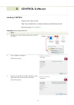
Page 115: ...ollow the steps in Procedure 9 Procedure 9 Installing CONTROL Action 1 On the PC launch the installer package and then click the Run button 2 The installation wizard appears Click Next to continue 3 Accept to use the default installation directory or select another directory by clicking the Browse button Click Next to continue Installer ...

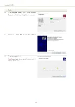
Page 116: ...Next to continue 5 Read the End User License Agreement and check I accept the license box Not checking the box ends the installation wizard Click Next to continue 6 The wizard creates a start menu folder with program short cuts Use the default name or enter a new name for the folder Click Next to continue Action 2 ...

Page 117: ...lick Next to continue 8 Check the Run the Silicon Labs CP10x driver installation box and click Next Note If you do not have the driver installed USB connectivity will fail 9 Click Install to install NKTP CONTROL software on your PC Click Cancel if you want to abort the installation Action ...

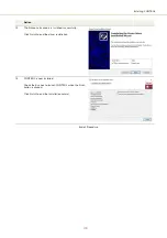
Page 118: ...ess meter for the installation Note a normal install should only take a few seconds 11 Click Next to install the UART drivers for the PC USB port 12 The drivers are installed Note Depending on your computer this occurs so fast you may not see this Action ...

Page 119: ... drivers is installed successfully Click Finish to end the driver installation 14 CONTROL is now installed Check the Run box to launch CONTROL when the Finish button is clicked Click Finish to end the installation wizard End of Procedure Action ...

Page 120: ...Installing CONTROL 120 ...

Page 121: ...ter is equipped with a B type USB port that typically connects to a PC using a standard Type A to Type B USB cable Note To connect a PC to the adapter NKTP s USB serial adapter software must be installed on the PC Power The adapter also provides a two pole power input socket to connect with an included external power supply The connected DC supply powers the adapter and also provides power to the ...

Page 122: ...ash Green Adapter receives RS 485 data from laser Emission Off No laser emission ON Red Laser emission enabled 1 Not used 4 12 VDC power input 2 USB type B connector 5 DB 15 laser interface see Main electrical interface on page 113 3 Status LEDs 6 Interlock connection and jumper 1 2 3 4 5 6 To PC To laser Interlock open emission disabled Interlock defeated emission permitted Interlock jumper posit...

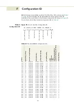
Page 123: ...Linewidth iv Piezo v Polarization Maintaining vi Enhanced Vibration Immunity vii Product Revision Y10 10 FCPGT FCPGT 1 5 N S S P A 0 Y10 10 FCPGT FCPGT 1 5 N S S P A 0 Y10 10 FCPGT FCPGT 1 5 N S S P A 0 Y10 10 FCPGT NONE 0 5 N S S P A 0 Y10 10 FCPGT NONE 0 5 N S S P A 0 Y10 10 FCPGT NONE 0 5 N S S P A 0 Y10 10 FCPGT FCPGT 1 5 N R S P A 0 Y10 10 FCPGT FCPGT 1 5 N R S P A 0 Y10 5 FCPGT FCPGT 1 5 N R...

Page 124: ...ame as in footnote i but also includes the option NONE iii Y yes includes a VOA N no no VOA included iv S Standard R Reduced v S Standard Piezo N Non Piezo vi P Polarization Maintaining PM N Non PM see vii A No wide thermal tuning range C Yes narrow thermal tuning range Variant Output Power mW Wavelength nm vacuum Connector type i Monitor output type ii Pigtail Length m VOA iii Linewidth iv Piezo ...

Page 125: ......

Page 126: ...Item 800 601 01 Customer Revision 1 5 NKTP Revision 2 0 Release Date 2022 03 ...

Reviews: