Connecting modulation signals
100
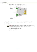
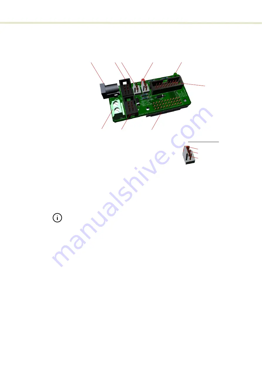
Figure 68
BASIK interface board
Note:
If desired, the Koheras BASIK can connect directly to a system main board
if it supports a DIN 41612 female C/3 connector.
DC Input Connector
As an alternative to the 2-pin screw terminal, the module can be connected to 12
volts DC using the 2.1 mm barrel type DC input connector. Connect 12 VDC to the
center pin and ground to the outer ring of the barrel connector.
ISP
The In-Serial-Programming 6-pin IDC connector is only for factory use – do not
connect.
Wavelength modulation input/output
The interface board includes a 3 pin Molex 2.54 mm KK-connector to connect
wavelength modulation input or output signals – see Modulation pins in
.
1.
DC input connector
6
Interbus
2.
ISP
7
2-pin screw terminal
3.
Wavelength modulation input/output
8
Extra I/O
4
Emission indicator LED
9
DIN 41612 female C/3
5.
LED
9
8
7
1
2
Wav
6
Wavelength-
-
3
4
GND
Modulation pins (3)
5
Summary of Contents for Koheras BASIK
Page 6: ...6 ...
Page 14: ...14 ...
Page 18: ...18 ...
Page 20: ...20 ...
Page 22: ...22 ...
Page 36: ...Module labels 36 ...
Page 46: ...External cavity stabilization BASIK X15 46 ...
Page 48: ...48 ...
Page 54: ...Connecting the SDK GUI to the laser 54 ...
Page 58: ...Controlling the laser emissions 58 ...
Page 90: ...Graphing 90 Figure 61 Graphing tab Y axis settings X axis ...
Page 92: ...92 ...
Page 104: ...Connecting the optical output 104 ...
Page 106: ...106 ...
Page 110: ...110 ...
Page 120: ...Installing CONTROL 120 ...
Page 125: ......
Page 126: ...Item 800 601 01 Customer Revision 1 5 NKTP Revision 2 0 Release Date 2022 03 ...


