Fast wavelength modulation
42
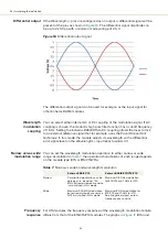
Differential output
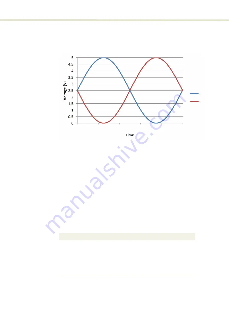
If the
Wav/-
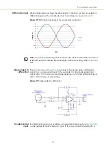
pins are configured as an output, a differential signal will be
present at the pins as shown in
. The differential signal amplitude can
be up to 2x 5 Vpp with a common mode voltage of 2.5 V.
Figure 16
Differential output signal
The differential output signal can be used for example, as the input signal for
other Koheras BASIK modules.
Wavelength
modulation
coupling
You can select either internal AC or DC coupling of the modulation signal. If AC
coupling is chosen, the module’s high pass filter function has a cut-off frequency
of 1.6 Hz. Setting the Koheras BASIK X15 to DC coupling allows the laser to lock
to an external reference signal that for example, uses the Pound Drever Hall
technique. In this mode, the module adjusts its wavelength so the differential
error signal level on the
Wav/-
input leans towards 0 V.
Narrow versus wide
modulation range
You can set the wavelength modulation operation to either narrow or wide
range. As detailed in
, the operation characteristic of each range depends
on the module type (X15 or E15/C15/Y15).
Table 7
Narrow vs wide band wavelength modulation
Frequency
response
For X15 modules, the frequency response of the wavelength modulation feature
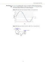
differs from that of the E15/C15/Y10 modules. The graphs in
(X15) and
Koheras BASIK X15
Koheras BASIK E15/C15/Y10
Narrow
Very limited modulation can be
obtained, i.e. maximum ~30
MHz. Extremely low phase noise
is maintained in this mode.
Maximum 0.8 GHz modulation
for E15/C15 and 1 GHz for Y10.
Wide
Maximum 500 MHz modulation,
but extremely low phase noise is
NOT maintained in this mode.
Maximum 8 GHz modulation for
E15/C15 and 10 GHz for Y10.
Small negative impact on low
frequency phase noise.
Summary of Contents for Koheras BASIK
Page 6: ...6 ...
Page 14: ...14 ...
Page 18: ...18 ...
Page 20: ...20 ...
Page 22: ...22 ...
Page 36: ...Module labels 36 ...
Page 46: ...External cavity stabilization BASIK X15 46 ...
Page 48: ...48 ...
Page 54: ...Connecting the SDK GUI to the laser 54 ...
Page 58: ...Controlling the laser emissions 58 ...
Page 90: ...Graphing 90 Figure 61 Graphing tab Y axis settings X axis ...
Page 92: ...92 ...
Page 104: ...Connecting the optical output 104 ...
Page 106: ...106 ...
Page 110: ...110 ...
Page 120: ...Installing CONTROL 120 ...
Page 125: ......
Page 126: ...Item 800 601 01 Customer Revision 1 5 NKTP Revision 2 0 Release Date 2022 03 ...


