Software Development Kit
50
Software Development Kit
NKT Photonics provides an SDK for use when integrating the laser with your
custom control system. You can download the SDK from the same URL where
CONTROL installer is found:
https://www.nktphotonics.com/lasers-fibers/support/software-drivers/
To install the SDK, run the installer and follow the instructions of the install
wizard.
Generic User
Interface
The installer includes the Generic User Interface software as part of the SDK.
This guide gives brief instructions on using the Generic User Interface to access
and modify registers containing operation parameters of the laser (see
Note:
For a full description of the SDK, registers and the Generic User Interface,
refer to the NKT Photonics document:
SDK Instruction Manual
. The manual is in-
stalled along with the SDK components when the SDK installer is run.
Connecting CONTROL to the laser
You can manage the laser using its RS-485 serial connection connected to a PC
with CONTROL installed on it. You can use the NKT Photonics RS-485
connection kit including the BASIK interface board to connect the laser to the
PC’s USB port. The kit is intended to help test the laser when integrating it with a
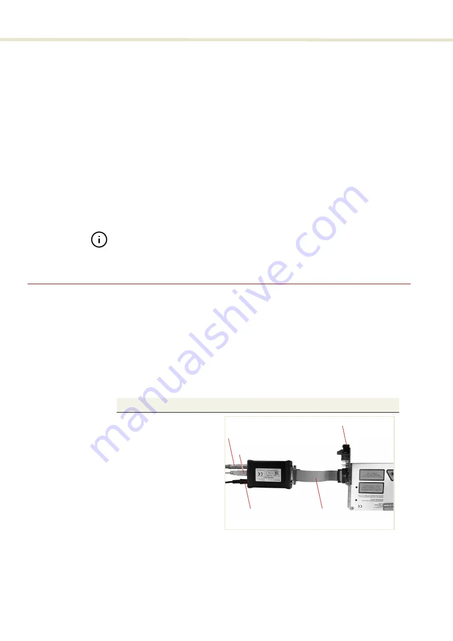
custom system. Follow the steps in
to connect CONTROL to the
laser using the kit.
Procedure 1
Connecting CONTROL to the laser
Action
1
a.
Connect a BASIK interface
board to the main interface
connector of the laser.
b.
Using an IDC 16 pin to DB-
15 ribbon cable, connect an
NKT Photonics RS-485
adapter to the 16 pin main
interface connector on the
BASIK interface board.
c.
Connect an RS-485 adapter
to your PC using a USB-A to
USB-B cable.
d.
To power on the laser,
connect the power supply
to the RS-485 adapter
power jack and AC mains.
Note
: Connect either a door safety switch circuit to the LEMO connection of the adapter
or use the adapter defeater shown in
.
Ribbon cable
USB to PC
12 VDC input
Interlock
BASIK interface board
2
Summary of Contents for Koheras BASIK
Page 6: ...6 ...
Page 14: ...14 ...
Page 18: ...18 ...
Page 20: ...20 ...
Page 22: ...22 ...
Page 36: ...Module labels 36 ...
Page 46: ...External cavity stabilization BASIK X15 46 ...
Page 48: ...48 ...
Page 54: ...Connecting the SDK GUI to the laser 54 ...
Page 58: ...Controlling the laser emissions 58 ...
Page 90: ...Graphing 90 Figure 61 Graphing tab Y axis settings X axis ...
Page 92: ...92 ...
Page 104: ...Connecting the optical output 104 ...
Page 106: ...106 ...
Page 110: ...110 ...
Page 120: ...Installing CONTROL 120 ...
Page 125: ......
Page 126: ...Item 800 601 01 Customer Revision 1 5 NKTP Revision 2 0 Release Date 2022 03 ...


