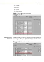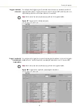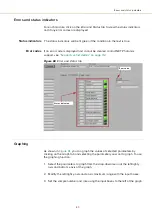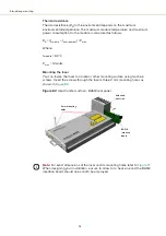
99
Connecting power
Connecting power
The RS-485 adapter kit includes an external power supply shown in
The power supply connects 12 volts DC output to the RS-485 adapter by means
of a two pole barrel connector. Power is delivered to the laser through the ribbon
cable from the adapter to the laser’s 16 pin main interface connector (via the
BASIK interface board). Refer to
for the laser’s pin
assignments.
Follow the instructions in
to connect power to the laser using the RS-
485 adapter.
Figure 67
Power supply
Table 12
Power adapter specifications
Connecting modulation signals
Input and output wavelength modulation signals are described in chapter 2:
. The signals are connected to or available from the pins on the rear
panel C/3 DIN connector, see
“Main electrical interface” on page 113
Alternatively if you are using the BASIK interface board refer to the following
section:
.
BASIK interface
board
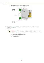
The BASIK interface board shown in
, provides a convenient method to
connect an external PC and other signals to the various PIN connectors on the
main electrical interface connector.
Item
Description
DC Output
12 V – 5 A
AC Input
100-240 VAC @ 50-60 Hz – 1.5 to 0.7 A
AC Connector
(inlet)
IEC 60320 – C6
DC Connector
2.5 mm Barrel (2.5x5.5x12)
Barrel Type
Connector
Summary of Contents for Koheras BASIK
Page 6: ...6 ...
Page 14: ...14 ...
Page 18: ...18 ...
Page 20: ...20 ...
Page 22: ...22 ...
Page 36: ...Module labels 36 ...
Page 46: ...External cavity stabilization BASIK X15 46 ...
Page 48: ...48 ...
Page 54: ...Connecting the SDK GUI to the laser 54 ...
Page 58: ...Controlling the laser emissions 58 ...
Page 90: ...Graphing 90 Figure 61 Graphing tab Y axis settings X axis ...
Page 92: ...92 ...
Page 104: ...Connecting the optical output 104 ...
Page 106: ...106 ...
Page 110: ...110 ...
Page 120: ...Installing CONTROL 120 ...
Page 125: ......
Page 126: ...Item 800 601 01 Customer Revision 1 5 NKTP Revision 2 0 Release Date 2022 03 ...

