background image

19


Front and rear panels

 CONTROL GUI

You can manage the BOOSTIK LC laser amplifier and all other modules inserted into 
an ACOUSTIK shelf using NKT Photonics CONTROL graphical user interface (GUI) 
software installed on a PC. The PC is connected to the ACOUSTIK through either an 
USB or Ethernet connection.

To connect to an access a BOOSTIK LC module,  follow the procedures to connect 
CONTROL to the ACOUSTIK shelf described in the document:

Koheras ACOUSTIK Product Guide

Once connected, use the software to control and monitor the amplifier emission. The 
amplifiers status and errors can also be viewed. For more information, refer to the 
chapter: 

“CONTROL GUI” on page 29

.

Generic UI and NKT

Photonics SDK

The Generic User Interface or Generic UI is control interface software intended for 
setting and monitoring the BOOSTIK LC registers. Registers are set or monitored 
through the Interbus protocol of the NKT Photonics SDK. 

The SDK and Generic UI are intended for integration of the laser with a custom-built 
control system. The Generic UI platform provides a convenient interface useful 
during development and deployment. Instructions on how to use the Generic UI and 
Interbus protocol can be found in the SDK user manual included with the kit. 

For BOOSTIK LC error codes and status bits, see 

Appendix D

.

Enabling emission

The BOOSTIK LC is intended for use as a component in an ACOUSTIK shelf as part 
of a complete laser system. To enable emission from the module, refer to the 
procedures in the document:

Koheras ACOUSTIK Product Guide

Summary of Contents for Koheras BOOSTIK LC

Page 1: ...Item 800 631 01 Koheras BOOSTIK LC PRODUCT GUIDE Narrow linewidth laser amplifier ...

Page 2: ...plifier housed in a line card form factor Koheras BOOSTIK LC 200 mW 1550 nm 200 mW narrow linewidrh line card amplifier housed in a line card form factor Koheras BOOSTIK LC 200 mW 1064 nm 200 mW narrow linewidrh line card amplifier housed in a line card form factor Koheras BOOSTIK LC Product Description Revision 1 1 10 2021 W 10456 ...

Page 3: ...ersonnel involved in the selection planning and deployment of lasers in laboratory and industrial settings The guide assumes a reasonable knowledge level of lasers photonic principles and electrical interface connectivity Chapters Inside This guide includes the following chapters Chapter I Description Describes the Koheras BOOSTIK LC laser amplifier module including its general operational descrip...

Page 4: ...on Caution Alerts you to a potential hazard that could cause loss of data or damage the system or equipment Warning The laser safety warning alerts you to potential serious injury that may be caused when using the laser Revision This section records the document revision history Release date Version and changes 2021 September 1st revision 2021 October Revision 1 1 Added the following CONTROL setti...

Page 5: ... panel 16 Rear panel 18 CONTROL GUI 19 Generic UI and NKT Photonics SDK 19 Enabling emission 19 BOOSTIK LC labels 21 2 Installation 23 Safety 23 Passive cooling 23 Rear panel 23 Left side panel surface 24 Custom mounting 24 Custom installation rules 25 Interlock 25 Fiber tip cleaning 26 Signs of damage 26 Damaged facet 27 Polishing 27 3 CONTROL GUI 29 ...

Page 6: ...OL menu 35 Key Updater tool 36 Log downloader 36 Extensions overview 38 Device monitor 39 Application log 40 Power mode 41 Current mode 41 Module overview 42 Toggling and sorting the overview fields 43 4 SDK Registers and Tabs 45 SDK installer 45 Read write registers 45 Output power setpoint 46 Emission 46 Setup bits 47 Stage one input monitor 48 Pump temperature 48 Heat sink temperature 49 Errors...

Page 7: ...ifications 53 B Service and Support Information 55 Servicing the laser 55 Opening the module 55 WARRANTY VOID IF REMOVED label 55 Support website 56 C Electrical interface pinout 57 D Fault troubleshooting 59 Contact support 59 E CONTROL installation 61 ...

Page 8: ...8 ...

Page 9: ...evice Monitor parameters 39 Table 6 Module overview fields 43 Table 7 Generic user interface registers 45 Table 8 Optical specifications 53 Table 9 Power consumption 53 Table 10 Mechanical dimensions 53 Table 11 Operating and storage environment 53 Table 12 Safety and regulatory compliances 53 Table 13 C 3 electrical interface pin descriptions 57 Table 14 Error codes 59 ...

Page 10: ...10 ...

Page 11: ...ue lint free 26 Figure 12 Optical fiber cleaning tool 26 Figure 13 CONTROL panels and menu 29 Figure 14 Panel dragged to a new location in the main window 30 Figure 15 Panels dragged outside the main window 30 Figure 16 Panels dragged outside the main window 31 Figure 17 Welcome screen and connecting 31 Figure 18 Device selector panel 32 Figure 19 Status panel indicators 32 Figure 20 CONTROL setti...

Page 12: ...nly monitor registers under the Readings tab 48 Figure 35 Stage one input monitor 48 Figure 36 Pump temperature 49 Figure 37 Pump 1 current 49 Figure 38 Error and status tab 50 Figure 39 Graphing tab 51 Figure 40 Mechanical dimensions front panel without faceplate 54 Figure 41 Mechanical dimensions side panel 54 Figure 42 Mechanical dimensions rear panel 54 Figure 43 Warranty seal 55 Figure 44 C 3...

Page 13: ...13 PROCEDURES Procedure 1 Relocating panels 30 Procedure 2 Using the Key Updater tool 36 Procedure 3 Using the Log Downloader 37 Procedure 4 Installing CONTROL 61 ...

Page 14: ...14 ...

Page 15: ...the 1060 1075 nm or 1545 1565 nm wavelength range Depending on the variant the amplifier is designed to extend the output power of its seed laser to either 200 mW or 2 W output power The amplifier achieves this while preserving the seed laser s ultra low noise and narrow linewidth optical output The rear panel of a BOOSTIK LC module includes an electrical connector The connector is designed to mat...

Page 16: ... following states Power the supply voltage status Interlock interlock circuit open closed not OK OK Emission the laser emission status enabled or disabled Status the module stability status For more information see Status LEDs on page 20 Variant 2 W 1550 nm 200 mW 1550 nm 200 mW 1064 nm Compatible Koheras seed laser s E15 X15 C5 E15 X15 C5 Y10 Operation mode CWi i Continuous Wave inherently single...

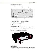
Page 17: ...ots Once inserted into the ACOUSTIK the module is fastened securely using four M4x0 7 screws Figure 3 Inserting a BOOSTIK LC into an ACOUSTIK shelf Input fiber connector A threaded E2000 input connector The connector is designed to received the seed optical signal from a BASIK module 1 Koheras ACOUSTIK faceplate 4 Output fiber and connector 2 Status LEDs 5 Handle 3 Input fiber connector from BASIK...

Page 18: ...apped holes for fastening the laser from the rear Figure 4 BASIK rear panel layout Main electrical Interface Caution The main electrical interface is a 30 pin male C 3 connector located on the rear panel of the module The interface includes pins for the following signals Serial communication RS 485 Interlock to support the Emission control Modulation input output wavelength modulation For a comple...

Page 19: ...29 Generic UI and NKT Photonics SDK The Generic User Interface or Generic UI is control interface software intended for setting and monitoring the BOOSTIK LC registers Registers are set or monitored through the Interbus protocol of the NKT Photonics SDK The SDK and Generic UI are intended for integration of the laser with a custom built control system The Generic UI platform provides a convenient ...

Page 20: ...dling and Regulatory Information Emission Interlock Status Power LED Name Condition Description Power ON Green DC Voltage at the DC power input pins is OK ON Red DC voltage at the DC power input pins is too low Flashing Amber The module is transmitting data OFF No DC power at the module power input pins Emission ON Red Laser amplifier emission is ON OFF Laser amplifier emission is OFF Status ON Gr...

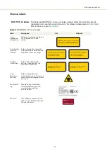
Page 21: ...ecifications the amplifier is capable of Laser Radiation Warning Safety information alert indicating this area of the laser is near a source of dangerous laser emissions Manufactur ing Manufacturing information including address part and serial number and date manufactured Warranty The module is sealed with this label It is prohibited to remove the chassis cover DESIGNATED FOR USE SOLELY AS A COMP...

Page 22: ...oduct information 6 Classification emission hazards WARNING INVISIBLE LASER RADIATION AVOID EXPOSURE TO BEAM CLASS 4 LASER COMPONENT MAXIMUM OUTPUT POWER 5W WAVELENGTH 900 2100 nm DESIGNATED FOR USE SOLELY AS A COMPONENT AND DOES NOT COMPLY WITH IEC 60825 1 OR 21 CFR 1040 10 AS A COMPLETE LASER PRODUCT WARRANTY VOID IF SEAL IS BROKEN OR REMOVED 4 5 1 6 2 3 ...

Page 23: ...orrosive agents or excessive moisture heat or dust Caution Table 11 in Appendix A lists the specifications for the BOOSTIK LC operating environment Rear panel The rear panel surface shown in Figure 7 acts as passive heat conductor for the module Using this surface the module must be mounted so that the surface is in contact with a heat conductive material and path to for example cooling fins When ...

Page 24: ...ling Figure 9 shows a custom passive cooling block mounted on the left panel The block is custom built and shown as an example only NKT Photonics only supplies cooling fins included on the rear of an Koheras ACOUSTIK shelf Figure 9 Custom passive cooling block mounted on the left panel Custom mounting As an example for a simple custom system the BOOSTIK LC module must be placed on a level and stab...

Page 25: ...ifier is placed on must be free of vibration or mechanical shocks Ensure to provide a thermal cooling path from either the rear or side panel Do not bend the fibers below a bend radius of 10 cm The amplifier is a Class 4 laser and as such the installation area must follow all regional laser safety regulations as defined by the assigned Laser Safety Officer LSO Interlock The BOOSTIK LC includes a s...

Page 26: ...specifically designed for use with optical fibers Always use extreme caution when cleaning fibers Examples of appropriate cleaning tools are Lens cleaning tissue lint free wipes see Figure 11 Optical fiber cleaning tool see Figure 12 Figure 11 Lens cleaning tissue lint free Figure 12 Optical fiber cleaning tool Signs of damage Indications of a damaged fiber facet may be due to one of the following...

Page 27: ...iber end however you must be careful not to over polish and generally NKTP recommends to return the unit for factory polishing The general procedure is to 1 Clean the connector and quickly and very lightly polish the connector end Caution Do not over polish the connector end fiber facet Over polishing the connector end will damage it due to its limited length 2 Clean the connector and then switch ...

Page 28: ...Polishing 28 ...

Page 29: ...atus panel on page 32 Menu items Four drop down menus with multiple functions CONTROL menu on page 35 Control panel The control panel provides controls for the laser The panel provides configuration controls such as wavelength pulse power and repetition rate Control panel on page 41 Application log This panel displays a debugging log that can be saved to a file Application log on page 40 Device mo...

Page 30: ...k panels to be displayed A blue check mark indicates the panel is displayed Action 1 Left click hold the top title bar of any panel 2 While holding the left mouse button down drag the panel to another position in the main window 3 When the background turns blue in a new GUI position release the mouse button to place the panel see Figure 14 4 Alternatively drag the panel outside the main window and...

Page 31: ...s are displayed when the laser connects to CONTROL Note To connect the PC to CONTROL refer to the document Koheras ACOUSTIK Product Guide Figure 17 Welcome screen and connecting Quick connect Alternatively click the quick connect button to scan the PC ports for compatible NKTP devices CONTROL connects to any valid device connected to the PC Device Selector Left click any icon in the device selecto...

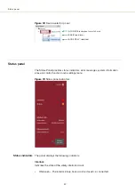
Page 32: ...ission control function and a settings menu Figure 19 Status panel indicators Status indicators The panel displays the following indicators Interlock Indicates the state of the safety interlock circuit ON Green The interlock loop back circuit is closed i e connected BASIK seed laser BOOSTIK LC selected ACOUSTIK rackmount smart chassis Click ...

Page 33: ...ber Laser Firmware Revision Note System info is only displayed if the option is checked in the View menu see View on page 35 Measurements The system temperature is displayed Note Measurements are only displayed if the option is checked in the View menu see View on page 35 Emission button The Emission button turns the laser amplifier emission ON The button indicator is lit steady ON RED when any la...

Page 34: ...ilable in the main Control panel and setpoint level of the output power is maintained by constant current fed to the amplifier Click the X in the upper right corner to close the panel and return to the main Control panel see Control panel on page 41 Figure 21 Power current mode settings Setting Item Function See Power current mode When selected the control panel allows you to set the amplifier to ...

Page 35: ...e name to display the items input field Menu Item Function See File Exits the CONTROL program Connect Disconnect Connect drop down selection of pre configured device connections to connect control to Disconnects the currently connected device from CONTROL Refer to the included CONTROL user help under Help Show Instruction Manual Tools Select from one of three special tools to use with your laser T...

Page 36: ...C main board do not support automatic download of log files For these modules you can use the Log Downloader tool to put the device into dedicated log download mode by enabling a collect log function Fast log vs slow log Both fast and slow log types collect the same data from the device The difference between the two logs is their polling resolution A fast log polls for data at a far shorter inter...

Page 37: ...percentage indicator shows the amount of log data collected for each module Logs are collected from each module The total collected percentage is displayed for the module s logs 3 To download and save a log file to the CONTROL PC right click the percentage indicator and select either Save log Immediately saves the fast or slow log file onto the CONTROL PC If the percentage shows less than 100 the ...

Page 38: ...short description of the release notes as seen in Figure 24 hover the mouse pointer over the Release notes text Note Multiple extensions for a wide range of NKTP lasers types and accessories are typically installed when using the default installation of CONTROL 5 If you select Collect Fast or Slow log the log is collected and saved in dedicated mode The CONTROL panel turns grey and all other funct...

Page 39: ...abled Status bits The actual status bits read from the connected module Error code The actual error code read from the connected module Access Protected Locked status of the module FW Ver The device module s firmware release date Module Serial The serial number of the device module PCB Serial The device module s printed circuit board serial number PCB Ver The version of the device module s printed...

Page 40: ...e log data using the buttons in the upper left corner Figure 25 Serial monitor The panel is enabled by placing a check mark on the Window drop down menu next to the Application Log item To close the panel click on the upper right corner X or uncheck it in the drop down menu CRC Total number of received telegrams with CRC failures COM Total number of communication errors with framing or protocol er...

Page 41: ...wer setpoint level using the slider control The level can be set from 10 to 100 of the maximum rated power You can additionally key in the power level directly by using the text input field at the upper right corner of the slider control Note Typically the maximum power exceeds the 100 rated value Figure 26 Power mode viewing and setting optical power Current mode When set to Current mode within t...

Page 42: ...ode viewing optical power Module overview When CONTROL connects to a Koheras ACOUSTIK shelf a Module overview panel is displayed beneath the Control and Status Panels As shown in Figure 28 each row in the overview represents an inserted module and the column fields display the module parameters and statuses Clicking on a row selects the actual module and switches to the Control and Status panel vi...

Page 43: ...Reference WL Base wavelength of the module in nm Actual WL Output wavelength of the module in nm WL offset Setpoint Wavelength offset set with CONTROL in pm Actual WL offset Measured wavelength offset in pm Status Module status indicator Power setpoint mW Power level set with CONTROL in mW Actual power mW Measured power level in mW Power setpoint dBm Power level set with CONTROL in dBm Actual Powe...

Page 44: ...Module overview 44 Figure 29 Module overview field selection Click any field to remove it click it again to add it back ...

Page 45: ...lowing URL https www nktphotonics com lasers fibers support software drivers Read write registers To to set and operate the BOOSTIK LC click on the Control tab in the left side half of the Generic UI window to view the read write registers For read write registers not described in this document refer to the SDK instruction manual included with the SDK installation Register name and link Function R...

Page 46: ...sing mW units use register 22 and for using dBm units used register A0 Figure 31 Setting the output power setpoint Emission Keying 1 into register 30 enables emission from the amplifier module If there is no input power Stage one input monitor then enabling emission fails and and a fault is raised with error code 60 displayed see Errors and status indicators on page 50 Readings 2 ...

Page 47: ...ers Figure 32 Enabling emission Setup bits Register 31 Setup bits configures the laser amplifier to operate in either current or power mode Set as follows 0000 Power mode 0001 Current mode Figure 33 Setting the setup bits ...

Page 48: ...Figure 34 Read only monitor registers under the Readings tab Stage one input monitor Readings register 10 displays the input power in mW received at the optical input of the laser amplifier Before enabling the amplifier emission ensure the minimum input power is displayed Figure 35 Stage one input monitor Pump temperature The hard coded pump temperature of the BOOSTIK LC is displayed in Readings r...

Page 49: ...write registers Figure 36 Pump temperature Heat sink temperature Register 1C displays the a temperature measurement from a sensor within the module near its rear passive cooling surface Figure 37 Pump 1 current ...

Page 50: ...rt contact details on page 90 Error codes are listed in Table 14 on page 59 Figure 38 Error and status tab Graphing As shown in Figure 39 you can graph the values of selected parameters by clicking on the Graph tab and selecting the parameter you want to graph To use the graphing function 1 Select the parameters to graph from the drop down menu at the left right y axis and bottom x axis of the gra...

Page 51: ...51 Graphing Figure 39 Graphing tab X axis setting Y axis settings ...

Page 52: ...Graphing 52 ...

Page 53: ...3 62 x 8 66 x 1 54 in Weight 1 kg 2 2 lb Operating Temperature internal case 15 C to 55 C 59 F to 131 F Storage Temperature 20 C to 60 C 4 F to 140 F Operating Humidity non condensing 20 to 80 FDA 21 CFR1040 10 Performance standards for light emitting products Safety Regulatory EN 60825 1 2014 Safety of laser products Part 1 Equipment classification and requirements Laser Class 4 EN 61010 1 2010 S...

Page 54: ...54 Figure 40 Mechanical dimensions front panel without faceplate Figure 41 Mechanical dimensions side panel Figure 42 Mechanical dimensions rear panel 2 ...

Page 55: ...contains electro static discharge ESD sensitive compo nents To avoid permanent ESD damage use ESD protection precautions when han dling it Always connect any earth point to a ground earth within your facility Opening the module There are no user serviceable components inside the module Should your laser amplifier malfunction and it cannot be serviced raise an RMA ticket request from the support si...

Page 56: ...IK LC laser or its accessories contact NKT Photonics through our support website below Support website 1 Go to https www nktphotonics com lasers fibers support technical support and customer service 2 Scroll down and click or press 3 Select the type of help required fill in the form and click or press Submit 2 ...

Page 57: ...ical Support B4 N C B9 AGND Analog ground for amplitude and wavelength modulation signals B10 AGND Analog ground for amplitude and wavelength modulation signals C1 Emission Collector output with internal 240 Ω resistor in series The output is high when the amplifier emission is ON An LED anode can be connected directly to this pin and the Cathode to GND to indicate emission externally C2 RS485 Pos...

Page 58: ...58 2 ...

Page 59: ...electrical cables are working properly 2 Contact support with error code and log files 7 Board temperature range Control board temperature out of range 1 Let the module cool down and provide proper cooling Retry emission 2 Contact support with error code and log files 8 Module disabled The module reporting the error is disabled with an interbus hardware signal 1 Retry emission 2 Check electrical c...

Page 60: ...port with error code and log files 65 Stage 1 current high Stage 1 current too high 1 Contact support with error code and log files 66 Stage 2 current high Stage 2 current too high 1 Contact support with error code and log files Code Name Description Solution perform in sequence 2 ...

Page 61: ... https www nktphotonics com lasers fibers support software drivers Follow the steps in Procedure Procedure 4 Installing CONTROL Action 1 On the PC launch the installer package and then click the Run button 2 The installation wizard appears Click Next to continue Installer ...

Page 62: ...button Click Next to continue 4 Uncheck the components you do not require By default all components will be installed Click Next to continue 5 ReadtheEnd UserLicenseAgreement andselect Iaccept the license Selecting I do not accept the license will end the installation wizard Click Next to continue Action 2 ...

Page 63: ...ram short cuts Use the default name or enter a new name for the folder Click Next to continue 7 Check the box to create a desktop shortcut to access Control Click Next to continue 8 Check the Silicon Labs driver installation recommended and click Next Action ...

Page 64: ...he installation Note a normal install should only take a few seconds 11 Click Next to install the UART drivers for the PC USB port 12 Read the End User License Agreement and select I accept this agreement Selecting Idon tacceptthisagreement willabortthedriver installation Otherwise check the agreement accept button and click Next to install the driver Action ...

Page 65: ... installed 14 The Silicon Labs drivers is installed successfully Click Finish to end the installation wizard 15 CONTROL is now installed Check the Run box to launch CONTROL when the Finish button is clicked Click Finish Action ...

Page 66: ...66 ...

Page 67: ......

Page 68: ...1 Koheras BOOSTIK LC Product Description Revision 1 1 10 2021 W 10456 ...

Reviews: